INSTALLATION
16
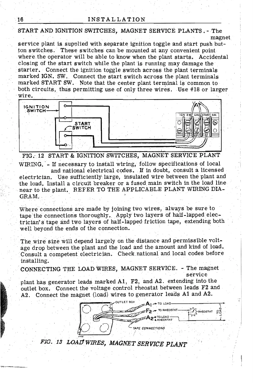
START
AND
IGNITION SWITCHES, MAGNET SERVICE PLANTS
,-
The
magnet
service
plant
is
supoUed with
separate
ignition
toggle
and
start
push
but-
jon
switches.
These
switches
can
be
mounted
at
any convenient point
where
the
operator
will
be
able
to
know when
the
plant
starts.
Accidental
closing
of the
start
switch
while
the
plant
is
running
may
damage
the
,
starter.
Connect
the
ignition toggle
switch
across
the
plant
terminals
marked
IGN.
SW
,Connect
the
start
switch
across
the
plant
terminals
marked
START
SW,
Note
that
the
center
plant
terminal
is
common
to
both
Circuits,
thus
permitting
use
of only
three
Wires. Use #18
or
larger
"wire.
IGNITION
',,'
~
'I
.
SW'TCH~
_ I "
.. .
..
~-s~-,~~-~
L,-
••
~I
=======~~
FIG.",12 START & IGNITION SWITCHES, MAGNET
SERVICEPLANT
WIRING, . -
If
~ecessary
to
install
wiring,
follow
specifications
of
local
and national
electrical
codes.
If
in doubt,
consulia
licensed
electrician,
Use
sufficientlyla.rge,
insulated
wire
between
the
plant
and
the
load.
Install
a
circuit
breaker
or
a
fused
main
switch
in
the
load
line
near
to
the
plant.
REFER
TO THE APPLICABLE PLANT WIRINGDIA-
GRAM.
Where
connections
are
made
by
joining
two
wires,
always
be
sure
to
tape
the
connections thoroughly.
Apply
two
layers
of
half-Iappedelec-
.
trician's
tape
and
two
layers
of
half-lapped
friction
tape,
extending both
well
beyond
the
ends of
the
connection.
The
wire
sizewill
depend
largely
on
the
distance
and
permissible
volt-
age
drop
between
the
plant
and the load and
the
amount and
kind
of
load.
Consult a
competenteiectrician.
Check.national and
local
codes
before
installing.
'
'cONNECTINGTHE
LOADWmES,
MAGNET SERVICE. -
The
magnet
service
.
plant
has
generator
leads
marked
A1, F2, and A2. extending into
the
outlet box. Connect
the
voltage
control
rheostat
between
leads
F2
and
A2. Connect
the
magnet (load)
wires
to
generator
leads
A1
and A2.
AI-TO
~~~~~:_~
~A2~~~~~~AT
..
CrAPE:
CONNECTIONS
F'IG. '13
LOAI1WIRES~MAGNET
SERVICE PLANT

 Loading...


