CT-1089-1a
RETAINER
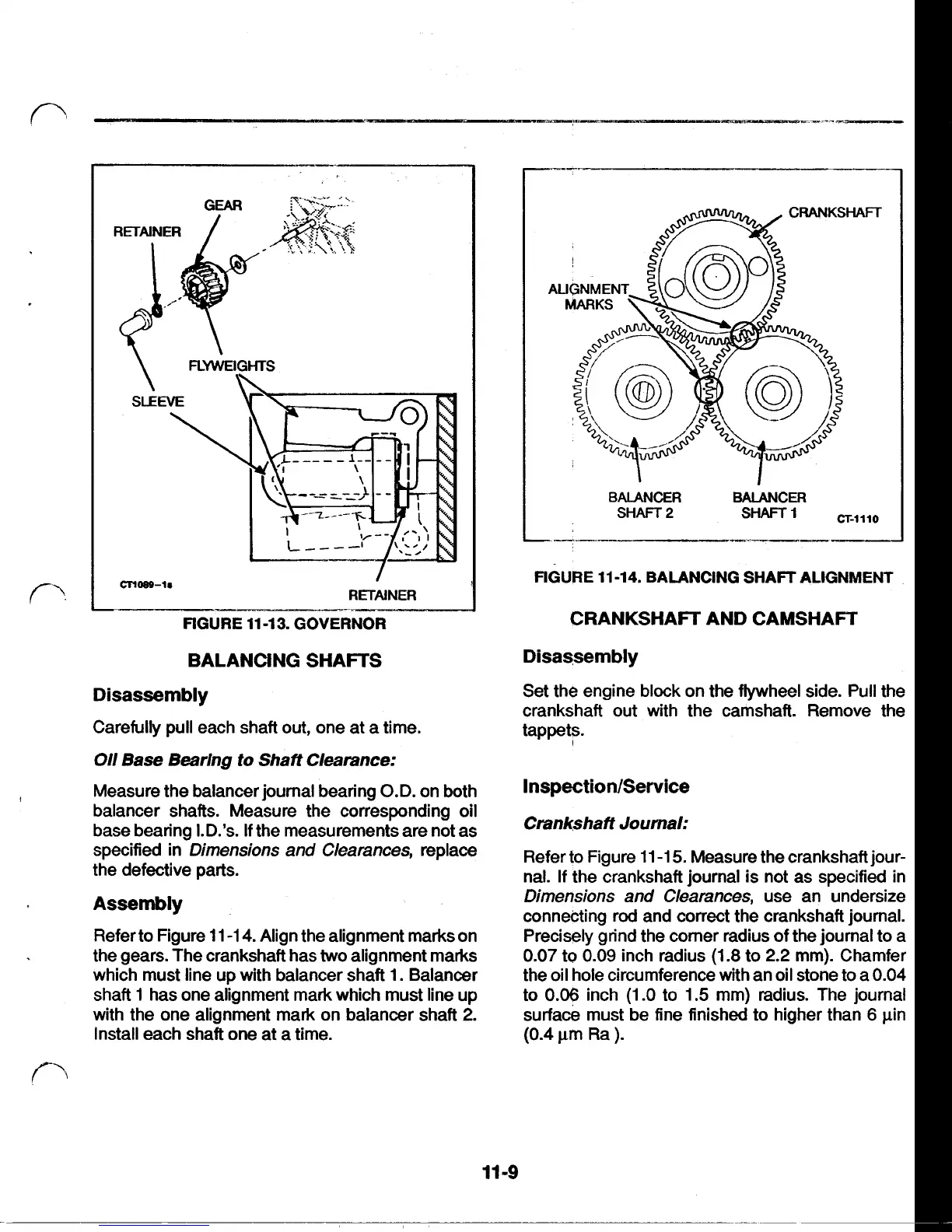
FIGURE 11-13. GOVERNOR
BALANCING SHAFTS
Disassembly
Carefully pull each shaft out, one at a time.
Oil
Base Bearlng
to
Shaft Clearance:
balancer shafts. Measure the corresponding
oil
base bearing
I.D.’s.
If
the measurements are not as
specified in
Dimensions and Clearances,
replace
the defective parts.
Assembly
Refer to Figure
11-14.
Align the alignment marks on
the gears. The crankshaft has
two
alignment marks
which must line up with balancer shaft
1.
Balancer
shaft
1
has one alignment mark which must line up
with the one alignment mark on balancer shaft
2.
Install each shaft one at a time.
Measure the balancer journal bearing
O.D.
on both
BALANCER
BALANCER
SHAFT
2
*-I
CT-1110
FIGURE 11-14. BALANCING
SHAFT
ALIGNMENT
CRANKSHAFT AND CAMSHAFT
Disassembly
Set the engine block
on
the flywheel side. Pull the
crankshaft out with the camshaft. Remove the
tappets.
Inspection/Service
Crankshaft Journal:
Refer to Figure
11-15.
Measure the crankshaft jour-
nal.
If
the crankshaft journal is not as specified in
Dimensions and Clearances,
use an undersize
connecting rod and correct the crankshaft journal.
Precisely grind the comer radius of the journal to a
0.07
to
0.09
inch radius
(1.8
to
2.2
mm). Chamfer
the oil hole circumference with an oil stone to a
0.04
to
0.06
inch
(1-0
to
1.5
mm) radius. The journal
surface must be fine finished to higher than
6
pin
(0.4
µm
Ra
).
11-9