ON
OFF
M1W
FIGURE
3-6.
IDLEMATIC
SWITCH
4.
Connect the AC loads to the receptacle(s) on the
control panel. Makesure the cord and plug connec-
tor have ground terminals.
Electrical shock can cause
severe personal injury or death.
Cord and plug equipment
must
have a ground fer-
minal
to
provide additional protection.
Adding
DC
Loads
Connect the DC loads to the DC receptacle on the
control panel. Make sure load wires positive
(+)
and
negative
(-)
match with the polarities at the receptacle
on the control panel. Refer to the Specification section
for maximum DC output current at 12 volts.
Batteries emit a highly explosive gas
that can be ignited by elecfrical arc-
ing, smoking, or other ignifion source. When charging
batteries, connect cables
fo
the battery before con-
necting cables
to
thegenera
for
set. This will reduce the
risk of arcing at the battery that could cause an explo-
sion. When battery charging
is
complefe, remove the
cable at fhe generator set before removing cables from
the battery.
Do
not use AC
receptacles
while using DC power
on
the following
models:
1.4
EGSAA,
1.7
EGHAA,
2.5
EGHAA,
CIRCUIT BREAKERS
If
either a DC or AC circuit breaker opens, check to see
if
the generator set is overloaded. If
so,
remove some of
the load from the generator set. Reset the circuit breaker
by pushing in the indicator (reset after waiting
a
min-
imum
of
10 seconds after tripping).
Ground-Fault
Circuit-Interrupter
Some models are equipped with a 120-volt GFCl outlet.
These outlets are intended for user protection. The
GFCl deenergizes the circuit
it
is
connected
to
when a
current to ground exceeds a predetermined value. If the
GFCl RESET button trips during operation, disconnect
ment for defects.
L
the load, stop the generator set, and inspect the equip-
Test the GFCl monthly by starting the generator set and
pressing the
TEST
button. If the RESET button pops
out,
push the
RESET
button back
in
to return the outlet to
normal operation.
If
the RESET does not pop
out,
the
GFCl
must be replaced.
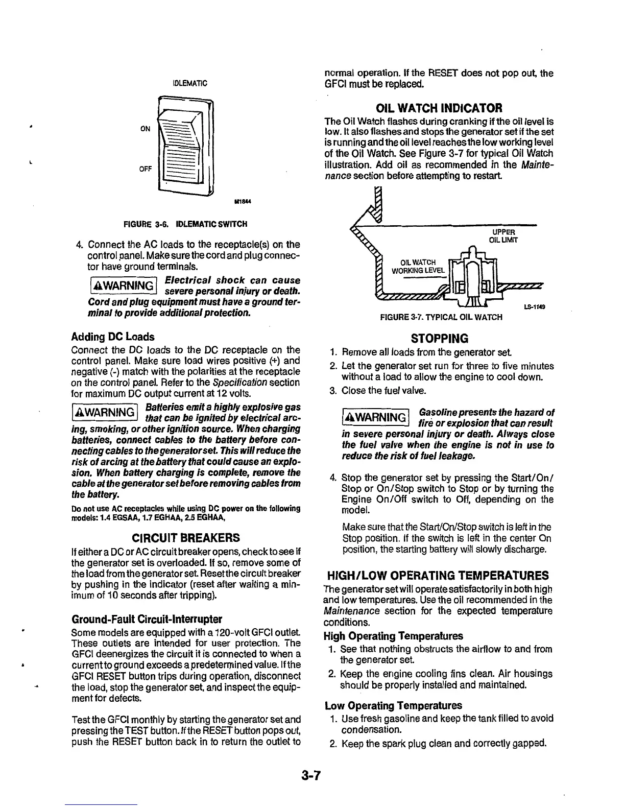
OIL
WATCH INDICATOR
The Oil Watch flashes during cranking
if
the oil level
is
low.
It
also flashes and stops the generator set if the
set
is running and the oil level reaches the
low
working level
of
the Oil Watch. See Figure
3-7
for typical Oil Watch
illustration. Add oil as recommended
in
the Mainte-
nance section before attempting to restart
UPPER
OIL
UMIT
FIGURE
3-7.
TYPICAL OIL WATCH
STOPPING
1.
Remove all loads from the generator set
2. Let the generator set run for three
to
five minutes
without a load to allow the engine to cool down.
3.
Close the fuel valve.
Gasoline presents the hazard of
fire
or
explosion that can result
in severe personal injury
or
death. Always close
the fuel valve when the engine is not in use
to
reduce the risk
of
fuel leakage.
4.
Stop the generator set by pressing the Start/Onl
Stop or On/Stop switch to Stop or by turning the
Engine On/Off switch to
Off,
depending on the
model.
Make sure that the Start/On/Stop switch is left in the
Stop position. If the switch
is
left in the center On
position, the starting battery
will
slowly
discharge.
HIGH/LOW OPERATING TEMPERATURES
The generator set will operate satisfactorily in both high
and low temperatures. Use the oil recommended in the
Maintenance section for the expected temperature
conditions.
High Operating Temperatures
1.
See that nothing obstructs the airflow to and from
2.
Keep the engine cooling fins clean. Air housings
the generator set.
should be properly installed and maintained.
Low Operating Temperatures
1.
Use fresh gasoline and keep the tank filled to avoid
2.
Keep the spark plug clean and correctly gapped.
condensation.
3-7