5-5
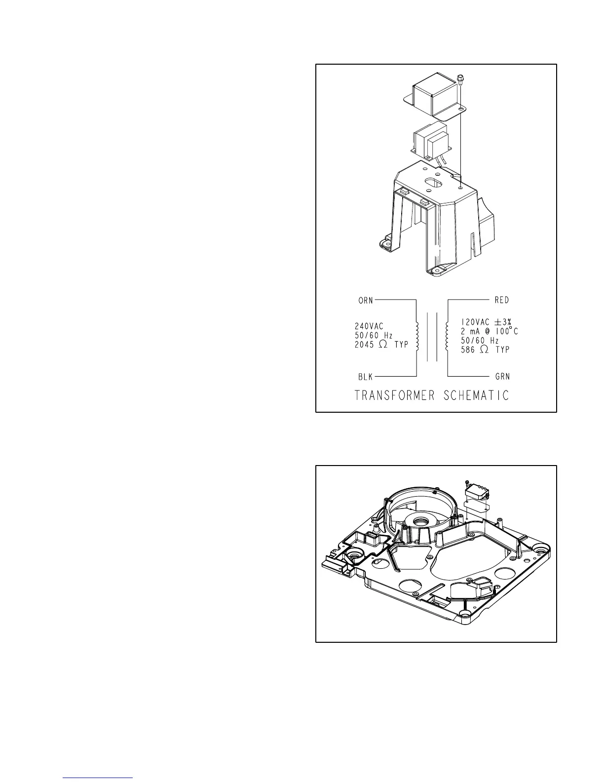
3-Phase Voltage Sense Transformer
Mounting: The voltage sense transformer for
3-phase generators is mounted as shown (Fig-
ure 5-6). It is connected as shown on Page 6-6 to
sense output voltage in L1.
Testing: Replace the transformer if resistance in ei-
ther winding is not as specified in the schematic.
Battery Charge Regulator VR
Mounting: When the genset is so equipped, the
regulator and heat sink are mounted as shown on
the engine-generator mounting base (Figure 5-7).
Testing: See Page 6-4 to test battery charge wind-
ing B1–B2. To test the regulator, remove the lead
from terminal B+. If B1–B2 output is 15 to 20 VAC,
but regulator output is less than 12.8 VDC, replace
regulator VR.
FIGURE 5-6. 3-PHASE VOLTAGE SENSE TRANS-
FORMER
FIGURE 5-7. BATTERY CHARGE REGULATOR VR
 Loading...


