5-6
Wiring Harness Ground Screw
Secure the four (4) GND wiring harness eyelets
(Page A-2 or A-4) to the base with the harness
ground screw (Figure 5-8).
Generator Neutral Ground Screw
For 2-Wire, 120 VAC gensets only (Figure 6-3,
Page 6-6), secure generator leads T2 and T4, the
green AC output lead and the two (2) white (L0 and
L0) AC output leads to the base with the generator
neutral ground screw (Figure 5-8).
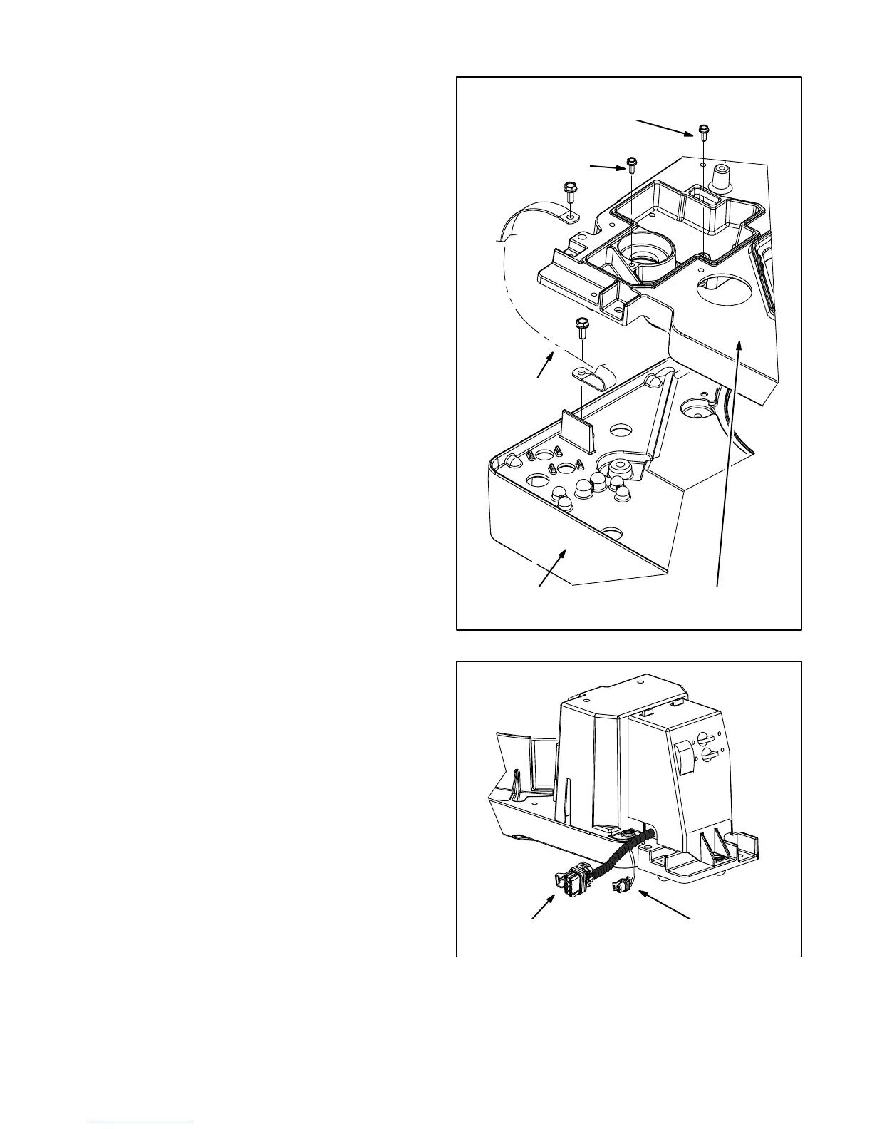
Bond Strap
Connect the bond strap (Figure 5-8) between the
generator/engine base and drip pan to carry control
and cranking currents to battery negative (–). The
negative battery cable terminal is on the bottom side
of the drip pan (Figure 5-13).
Remote Control Connector P2/J2
Figure 8-6 illustrates the sealed 8-pin connector for
remote control.
Fuel Pump Connector
Figure 8-6 illustrates the sealed 2-pin remote fuel
pump connector for Models HGJAA and HGJAD.
Models HGJAB, HGJAC, HGJAE and HGJAF gen-
sets have, instead, two (2) separate quick-connects
for connection directly to the leads of the mounted
gasoline fuel pump (Page 8-11) or LPG shutoff sole-
noid (Page 8-14).
BOND
STRAP
GENERATOR/ENGINE
BASE
DRIP
PAN
WIRING HARNESS
GROUND SCREW
GENERATOR NEUTRAL
GROUND SCREW
FIGURE 5-8. BOND STRAP
REMOTE CONTROL
CONNECTOR P2/J2
REMOTE FUEL PUMP
CONNECTOR (HGJAA / D)
FIGURE 5-9. REMOTE CONNECTORS
 Loading...


