8-3
Fuel Rail and Injectors
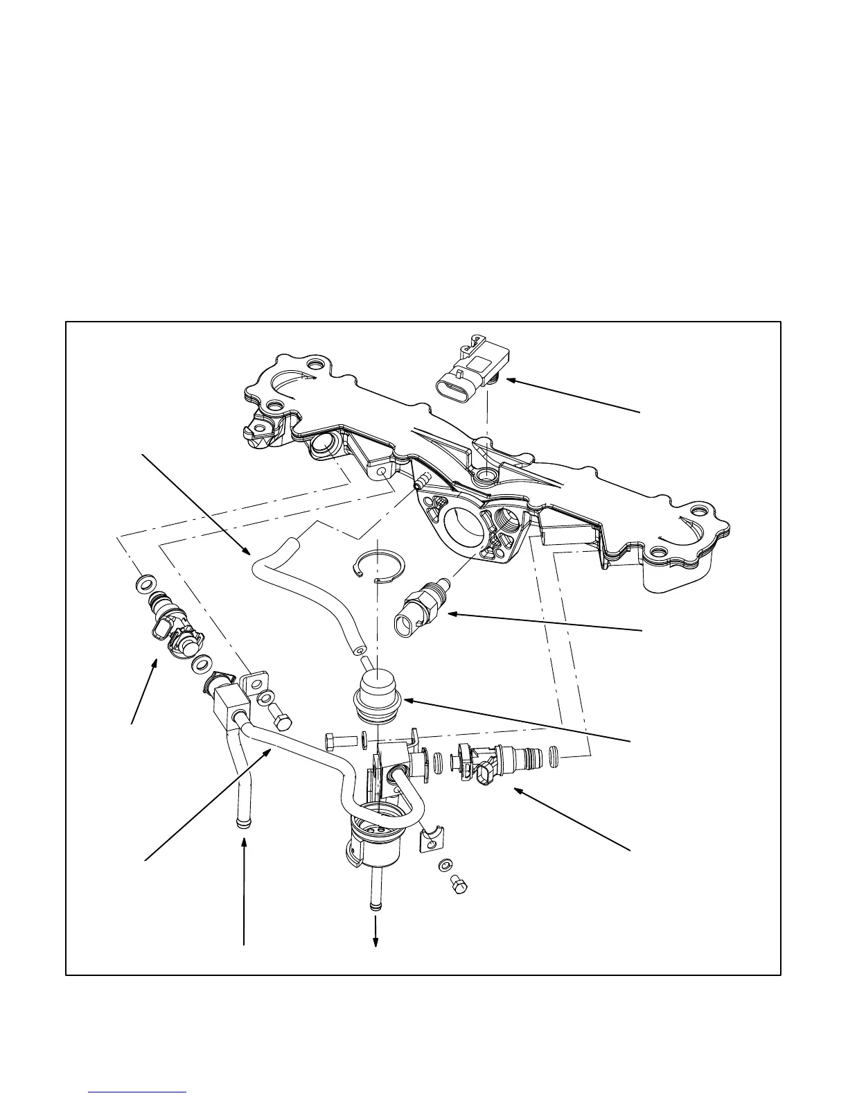
The rail-injector-regulator assembly (Figure 8-2) is
flexible enough to remove as an assembly from the
intake manifold. All of the components shown ex-
cept for the intake manifold and MAP sensor are re-
moveable without removing the genset enclosure.
Thoroughly clean the outside of the assembly be-
fore disassembly and be careful not to let dirt enter
fuel system components while disassembled..
Remove the throttle body (Figure 8-1), disconnect
the vacuum hose and remove the two mounting
screws. All joints have O-ring seals. To pull an injec-
tor from the fuel rail, gently pry apart the two sides of
the clip on the injector. Replace an injector if electri-
cal resistance is not approximately 12.5 ohms.
When reassembling, apply light motor oil (sparingly)
to the O-ring seals on the ends of the fuel injectors.
Push the injectors on by hand until they snap se-
curely in place on the fuel rail. Make sure the fuel rail
brackets line up with and seat firmly against the ma-
chined bosses on the manifold. Tighten the mount-
ing screws to 75 lb-in (8.4 N-m).
Make sure to reconnect the vacuum hose. Push the
ends on dry all the way up the hose barbs.
MAP
SENSOR
MAT
SENSOR
VACUUM
HOSE
FUEL
RAIL
FUEL SUPPLY FUEL RETURN
PRESSURE
REGULATOR
FUEL
INJECTOR
& O-RINGS
FUEL
INJECTOR
& O-RINGS
FIGURE 8-2. FUEL RAIL / INTAKE MANIFOLD ASSEMBLY
 Loading...


