8-4
Fuel Pressure Regulator
The fuel pressure regulator body (Figure 8-2) is re-
moveable from the rail assembly by disconnecting
the vacuum hose and removing the circlip.
Apply light motor oil (sparingly) to the two O-ring
seals when reassembling.
The manifold vacuum hose is connected to the back
of the regulator diaphragm to maintain a constant
fuel pressure differential across the fuel injectors as
intake manifold pressure varies. Make sure to re-
connect the vacuum hose. Push the ends on dry all
the way up the hose barbs.
MAT Sensor
Check electrical resistance across the two terminals
of the MAT sensor (Figure 8-2). Replace the sensor
if resistance is not 2600 to 3000 ohms. To remove
the sensor, remove the throttle body (Page 8-1),
disconnect the wiring harness and unthread it from
the manifold.
When reinstalling the sensor apply Teflon thread
coating to the threads of the sensor. Turn it in until
just two threads are left.
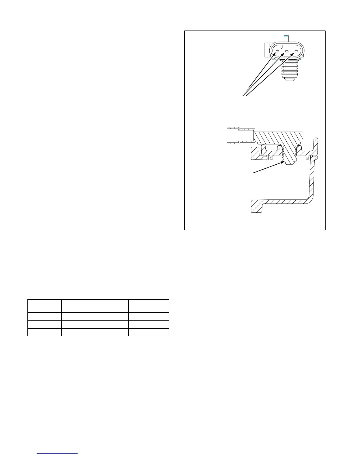
MAP Sensor
The genset enclosure must be removed to remove
the MAP sensor, which is pulled straight up to re-
move it from the intake manifold (Figure 8-2). To
check electrical resistances across the pins indi-
cated in Figure 8-3, remove the connector. To deter-
mine the letter designation of a pin, check the mark-
ing on the corresponding connector lead. Replace
the sensor if any reading is out of specification
(Table 8-2).
TABLE 8-2 MAP SENSOR RESISTANCES
PINS
KILO-OHMS @ Room
Temperature & Pressure
CONNECTION
A-C 4.0-4.2 GND-5V
A-B 91-101 GND-V
out
B-C 91-97 V
out
-5V
When reinstalling the sensor, apply light motor oil
(sparingly) to the the sealing grommet and push it in
by hand. Make sure the grommet is all the way
through the hole so that it will not come out (Fig-
ure 8-3).
MAKE SURE SEALING
GROMMET IS ALL THE
WAY THROUGH HOLE
CHECK ELECTRICAL RESISTANCES
ACROSS THESE TERMINALS
FIGURE 8-3. MAP SENSOR
 Loading...


