8-19
MECHANICAL GOVERNOR—HGJAB,
HGJAC, HGJAE, HGJAF
The mechanical governor (Figure 8-18) operates
the throttle plate in the carburetor or mixer to main-
tain constant engine speed (within a range of 5 per-
cent) as load varies. See Page 9-14 regarding the
internal governor parts.
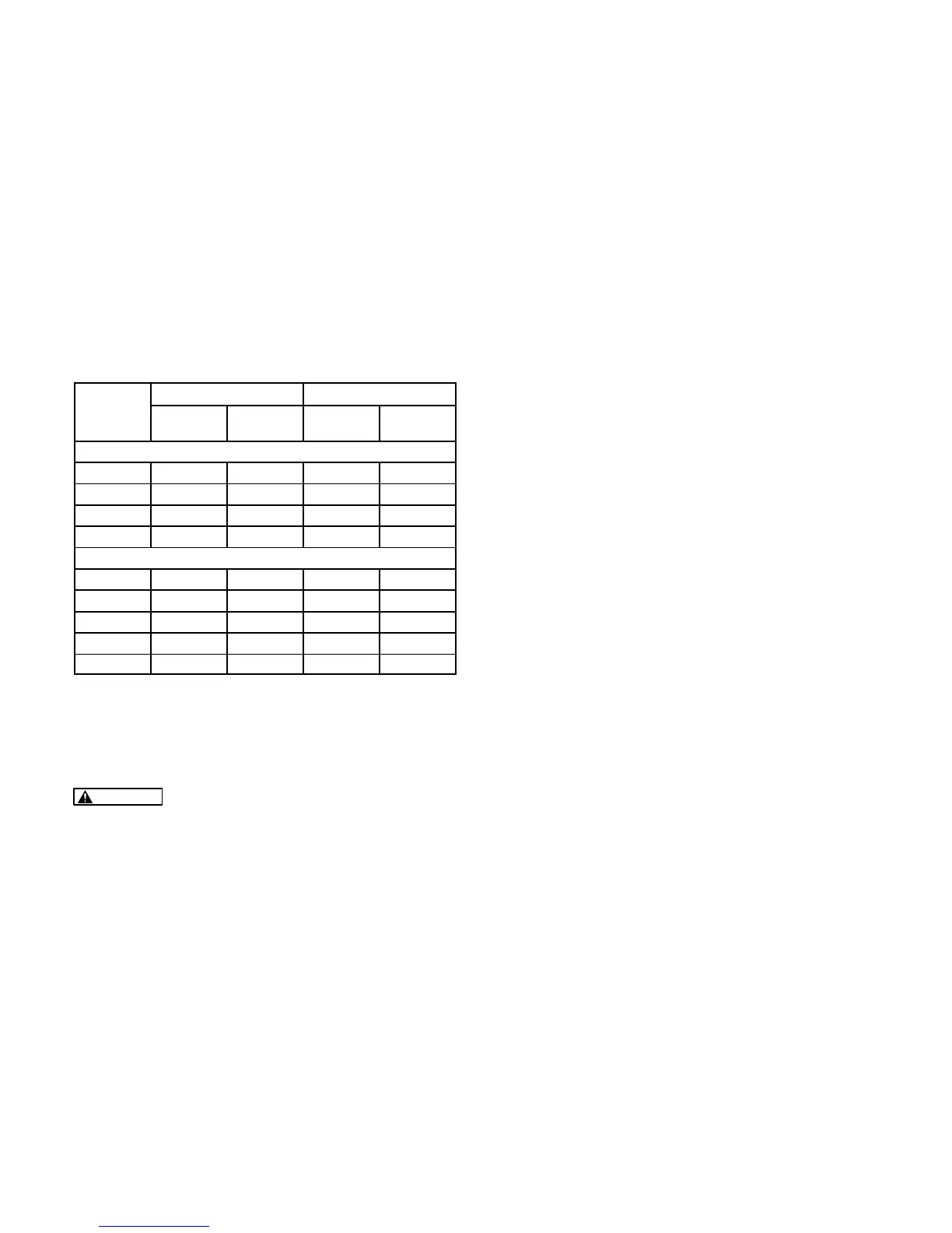
See Table 8-3 for rated voltage and frequency ver-
sus allowable voltage range and droop (the differ-
ence between No-Load frequency and Full-Load
frequency).
TABLE 8-3 VOLTAGE / FREQUENCY / DROOP
Voltage Frequency
ate
Voltage
Max No
Load
Min Full
Load
No Load Droop
60 HERTZ GENSETS
100 108 93 63/62 2–4
120 125 112 63/62 2–4
200 216 186 63/62 2–4
240 250 224 63/62 2–4
50 HERTZ GENSETS
100 108 93 52.5/51.5 2–4
200 216 186 52.5/51.5 2–4
220 238 205 52.5/51.5 2–4
230 249 215 52.5/51.5 2–4
240 250 224 52.5/51.5 2–4
Before making governor adjustments, check for oth-
er causes of hunting or excessive droop, such as
binding governor linkage, fouled spark plugs, im-
proper valve lash, and dirty fuel filters.
CAUTION
Voltage/frequency-sensitive equip-
ment such as VCRs, televisions, computers,
etc. may be damaged by power line frequency
variations. Some solid-state devices are pow-
ered whenever connected to an AC outlet even if
the device is not in actual operation. For this
reason, disconnect all devices which are volt-
age or frequency-sensitive before attempting
any carburetor/governor adjustments. If dis-
connecting the devices is not possible, open
the circuit breaker(s) at the distribution panel or
at the genset, if so equipped.
Accurate governor adjustments require a variable
load bank of up to 7 kW capacity and accurate me-
ters for measuring frequency (within 0.3%), voltage
(within 0.5%) and output current (AC).
Assembling Governor Linkage
Reassemble the throttle link and its tension spring if
they have not been assembled as shown in Fig-
ure 8-18. The easiest way is to hook both ends of
link and spring while the governor arm is detached.
Hook the tension spring below the throttle link in the
throttle lever so that it can pull down on the bottom of
the hole while the throttle link can push up on the top
of the hole without interfering with each other.
To detach the governor arm, remove the governor
shaft nut by turning it clockwise and then pull the
arm away from the shaft hub. To reattach the arm,
see Resetting Governor Arm.
Resetting Governor Arm
Anytime the carburetor or governor linkage has
been disturbed by disassembly and reassembly, it
will be necessary to reset the governor arm on the
governor shaft, as follows (see Figure 8-18):
1. Loosen the governor shaft nut by turning it
clockwise and remove the arm.
2. Use a battery terminal puller or equivalent tool
to break the taper fit of the shaft in the arm hub.
3. Reattach arm and hub, making sure the two
pins and holes engage, and thread the shaft nut
on counterclockwise. Check for free rotation
of the arm around the shaft and let the governor
spring take up all play in the linkage. The link-
age must push the throttle up against the wide
open throttle stop.
4. Torque the shaft nut to 8 lb-ft (11 N-m), coun-
terclockwise. (By design, tightening counter-
clockwise takes up play between the internal
governor parts.)
5. Gently push the governor arm down and check
for binding, rubbing against adjacent parts, in-
terference with wiring and looseness.
Adjusting Governor
Adjust the governor as follows (see Figure 8-18):
1. Warm up the genset for at least 5 minutes at 1/2
to 3/4 rated load. The choke must be complete-
ly open. Adjust frequency as close as possible
to the appropriate Table 8-3 value with the
speed adjusting nut to keep the genset from
shutting down (most likely on Fault 14—Over-
frequency or Fault 15—Underfrequency). Re-
start in 5 seconds if it shuts down.
 Loading...


