8-20
2. When the engine is warm remove all loads and
adjust the idle (throttle) stop screw to obtain
51 to 53 Hz on a 60 Hz genset or 41 to 43 Hz
on a 50 Hz genset, holding down the throttle le-
ver with your finger.
3. Let the throttle lever go and recheck and re-
adjust No-Load frequency (speed), as neces-
sary, to Table 8-3. Bump the governor arm to
see that frequency stabilizes.
4. Connect rated load. If droop is greater than
specified in Table 8-3, move the governor
spring hook one or two notches towards the
governor shaft and recheck frequency and
droop. Repeat the procedure as necessary. If
droop is less than specified, or the genset
hunts, move the spring hook one or two
notches away from the governor shaft and re-
check frequency and droop. Repeat the proce-
dure as necessary.
5. The governor must not hunt. Check for hunting
under the following loading sequence:
A.
No-Load • 3/4-Load • No-Load • 1/2-Load •
No-Load • 1/4-Load • No-Load.
6. See see Section 11. Troubleshooting if output
voltage does not fall within the range specified
in Table 8-3.
7. Check for binding, interference with wiring and
rubbing against adjacent parts. Reset the gov-
ernor arm if governor performance does not im-
prove.
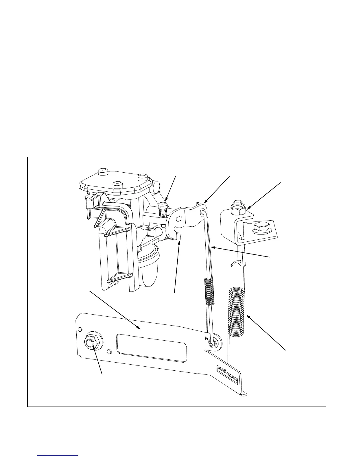
IDLE (THROTTLE)
STOP SCREW
GOVERNOR
ARM
SPEED
ADJUSTING
NUT
GOVERNOR
SPRING
THROTTLE LINK
& TENSION
SPRING
THROTTLE LEVER
(WIDE OPEN)
WIDE OPEN
THROTTLE
STOP
GOVERNOR SHAFT NUT
IMPORTANT: CLOCKWISE TO LOOSEN,
COUNTERCLOCKWISE TO TIGHTEN
FIGURE 8-18. MECHANICAL GOVERNOR
 Loading...


