0
Splash Fouled
-
Check for accumulated combus-
tion chamber deposits. See Cylinder Head section.
0
Light Tan or Gray Deposits
-
Normal plug color.
If
the spark
plug
is in good condition,
proceed
to
the Ignition
Coil section.
SPARK
PLUG
GAP
-(SEE
SPECIFICATIONS)
ES-1462
FIGURE
6-4.
MEASURING PLUG GAP
Ignition Coil
(TI)
The ignition coil is a transformer that steps up the mag-
neto output voltage to about
20,000
volts for spark plug
firing. The coil consists of a primary and a secondary
winding. Perform the following checks:
Ignition
Spark Check:
1.
Make sure the engine oil level is adequate and that
the genset
is
level.
2.
Remove the spark plug, reconnect the spark plug
lead and ground the plug side electrode to bare
metal on the engine.
3.
Do
not touch the plug or plug wire during testing.
Crank the engine and observe the plug. A good
spark should be observed.
If
no spark is observed,
proceed to the coil winding check.
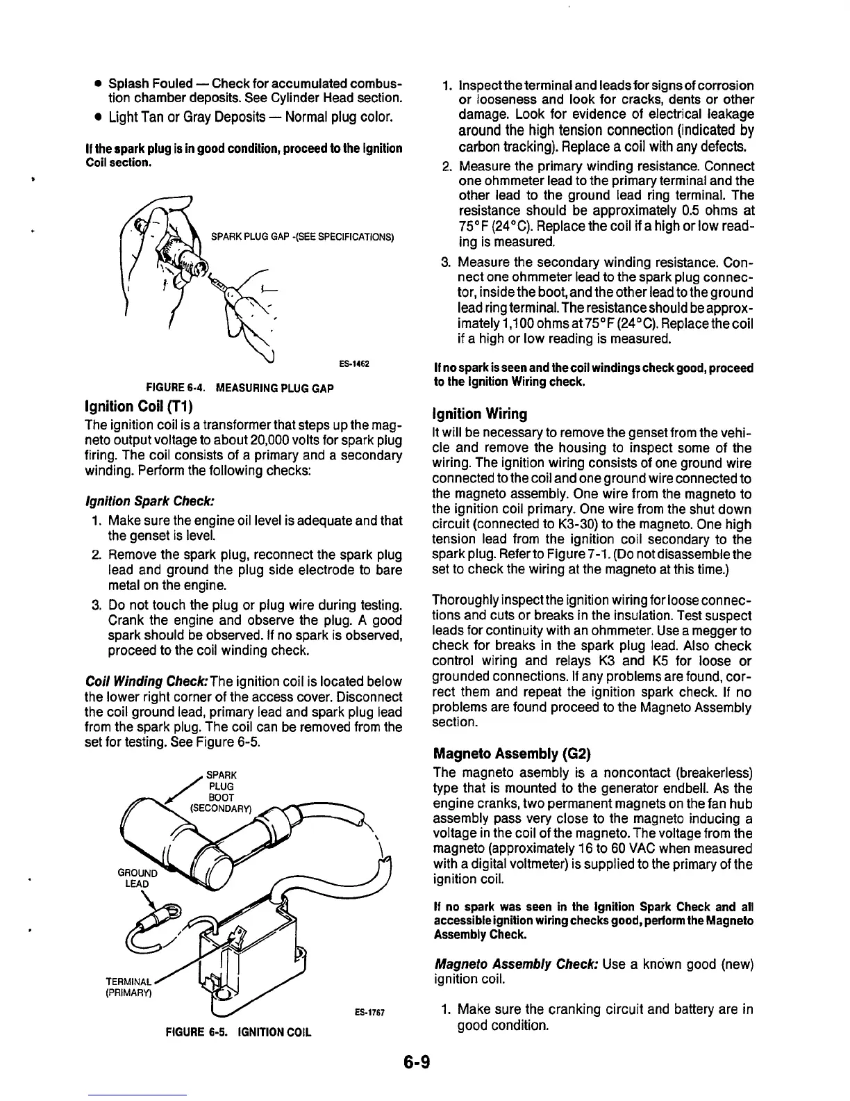
Coil
Winding
Check:The ignition coil is located below
the lower right corner
of
the access cover. Disconnect
the coil ground lead, primary lead and spark plug lead
from the spark plug. The coil can be removed from the
set for testing. See Figure
6-5.
SPARK
rwti
BOOT
.
TERMINAL/
1
(PRIMARY)
1.
2.
3.
Inspect the terminal and leadsfor signs
of
corrosion
or
looseness and look for cracks, dents or other
damage. Look for evidence
of
electrical leakage
around
the high
tension
connection (indicated
by
carbon tracking). Replace
a
coil with any defects.
Measure the primary winding resistance. Connect
one ohmmeter lead
to
the primary terminal and the
other lead to the ground lead ring terminal. The
resistance should be approximately
0.5
ohms at
75OF (24°C). Replace the coil if a high or low read-
ing
is
measured.
Measure the secondary winding resistance. Con-
nect one ohmmeter lead to the spark plug connec-
tor, inside the boot,and the other lead to the ground
lead ring terminal. The resistance should be approx-
imately 1,1000hmsat75°F(240C). Replacethecoil
if
a high or low reading is measured.
If
nospark
is
seen and the coil windings check good, proceed
to
the Ignition Wiring check.
ignition Wiring
It will be necessary to remove the genset from the vehi-
cle and remove the housing to inspect some of the
wiring. The ignition wiring consists of one ground wire
connected to the coil and one ground wire connected to
the magneto assembly. One wire from the magneto to
the ignition coil primary. One wire from the shut down
circuit (connected to
K3-30)
to the magneto. One high
tension lead from the ignition coil secondary to the
spark plug. Refer to Figure 7-1.
(Do
not disassemble the
set to check the wiring at the magneto at this time.)
Thoroughly inspect the ignition wiring for loose connec-
tions and cuts or breaks in the insulation. Test suspect
leads for continuity with an ohmmeter. Use a megger
to
check for breaks in the spark plug lead. Also check
control wiring and relays K3 and
K5
for loose
or
grounded connections.
If
any problems are found, cor-
rect them and repeat the ignition spark check.
If
no
problems are found proceed to the Magneto Assembly
section.
Magneto Assembly
(G2)
The magneto asembly is a noncontact (breakerless)
type that is mounted
to
the generator endbell. As the
engine cranks, two permanent magnets on the fan hub
assembly pass very close to the magneto inducing a
voltage in the coil of the magneto. The voltage from the
magneto (approximately
16
to
60
VAC when measured
with a digital voltmeter) is supplied to the primary of the
ignition coil.
If
no spark
was
seen in the Ignition Spark Check and all
accessible ignition wiring checks good, perform the Magneto
Assembly Check.
Magneto
Assembly Check: Use a known good (new)
ignition coil.
W
ES-1767
FIGURE
6-5.
IGNITION
COIL
1.
Make sure the cranking circuit and battery are in
good condition.
6-9

 Loading...
