1.
Remove the brush block mounting screws and
lift
2.
Remove
brushes
and
springs from holder and
out the brush block.
replace with new parts (see Figure 8-8).
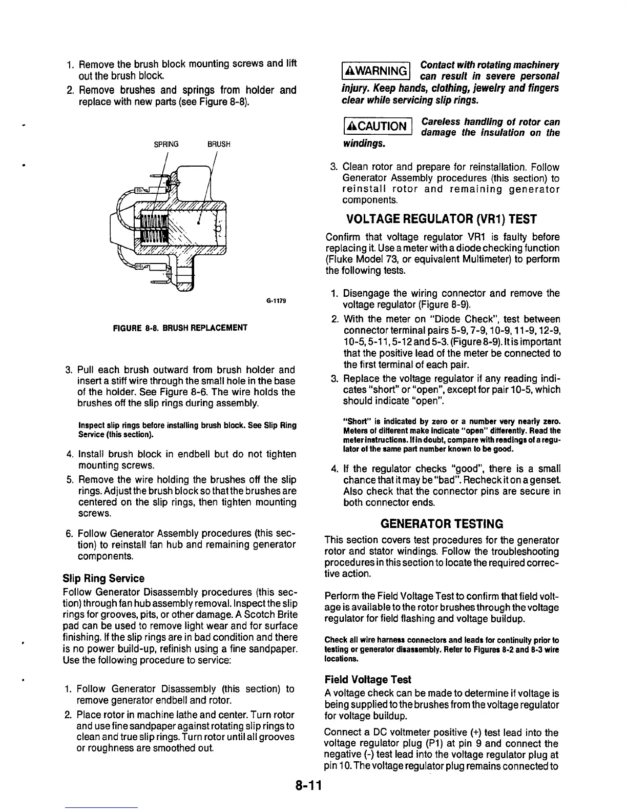
SPRING
BRUSH
I
6-1179
FIGURE
8-8.
BRUSH
REPLACEMENT
3.
Pull each brush outward from brush holder and
insert a stiff wire through the small hole in the base
of the holder. See Figure
8-6.
The wire holds the
brushes
off
the slip rings during assembly.
Confact with rotating machinery
llEEE%l
can
result
in
severe
personal
injury.
Keep
hands,
cloihing,
jewelry
and
fingers
clear
while
servicing slip rings.
ACAUT~ON
Careless handling
of
rotor
can
D
damage the insulation on the
windings.
3.
Clean rotor and prepare for reinstallation. Follow
Generator Assembly procedures (this section) to
reinstall rotor and remaining generator
components.
VOLTAGE REGULATOR
(VR1)
TEST
Confirm that voltage regulator VR1 is faulty before
replacing it. Use a meter with adiodechecking function
(Fluke Model
73,
or equivalent Multimeter) to perform
the following tests.
1. Disengage the wiring connector and remove the
voltage regulator (Figure 8-9).
2.
With the meter on “Diode Check”, test between
connector terminal pairs 5-9,7-9.10-9,11-9,12-9,
10-5,5-11 5-12 and
5-3.
(Figure8-9).
It
is important
that the positive lead of the meter be connected to
the first terminal of each pair.
3.
Replace the voltage regulator
if
any reading indi-
cates “short” or “open”. except for pair
10-5,
which
should indicate “open”.
,
Inspect slip rings before installing brush block.
See
Slip Ring
Service (this section).
4.
Install brush block in endbell but do not tighten
mounting screws.
5.
Remove the wire holding the brushes
off
the slip
rings. Adjust the brush block
so
that the brushes are
centered on the slip rings, then tighten mounting
screws.
6.
Follow Generator Assembly procedures (this sec-
tion) to reinstall fan hub and remaining generator
components.
Slip
Ring
Service
Follow Generator Disassembly procedures (this sec-
tion) through fan hub assembly removal. Inspect the slip
rings for grooves, pits, or other damage. A Scotch Brite
pad can be used
to
remove light wear and for surface
finishing.
If
the slip rings are in bad condition and there
is no power build-up, refinish using a fine sandpaper.
Use the following procedure
to
service:
“Short” is indicated by zero or a number very nearly zero.
Meters
of
diflerent make indicate “open” differently. Read the
meter instructions.
If
in doubt, compare with readings
of
a regu-
lator
of
the same part number known to
be
good.
4.
If the regulator checks “good”, there is a small
chance that it may be”bad”. Recheck it on agenset.
Also
check that the connector pins are secure in
both connector ends.
GENERATOR TESTING
This section covers test procedures for the generator
rotor and stator windings. Follow the troubleshooting
procedures in this section
to
locate the required correc-
tive action.
Perform the Field Voltage Test to confirm that field volt-
age is available to the rotor brushes through the voltage
regulator for field flashing and voltage buildup.
Check all wire harness connectors and leads
for
continuity
prior
to
testing
or
generator disassembly. Refer to Figurer
8-2
and
8-3
wire
locations.
1.
2.
Field
Voltage Test
being supplied to the brushes from the voltage regulator
for voltaae builduD.
Follow Generator Disassembly (this section) to
A voltage check can be made to determine
if
voltage is
remove generator endbell and rotor.
Place rotor in machine lathe and center. Turn rotor
I
Connect a DC voltmeter positive
(+)
test lead into the
voltage regulator plug
(Pl)
at pin
9
and connect the
negative (-)test lead into the voltage regulator plug at
pin
10.
The voltage regulator plug remains connected to
and use fine sandpaper against rotating slip rings to
clean and true slip rings. Turn rotor until all grooves
or roughness are smoothed out.
8-1
1

 Loading...
