GOVERNOR
With the crankcase cover removed, the governor can be
inspected or disassembled for service. The governor
assembly must spin freely on the center pin without
excessive looseness or wobble. Sleeve tip wear is the
most
common cause of governor failure.
If
governor
sleeve, gear, or flyweights are worn or otherwise dam-
aged replace them. To disassemble, remove the snap
ring from the governor center pin and slide governor
gear assembly
off
mounting shaft being careful not
to
lose outer washer. See Figure9-14. To install governor,
assemble in reverse order of removal (see inset draw-
ing, Figure 9-14, for position of flyweight and sleeve).
v
CT-1090
To remove the governor shaft, remove the retainer clip
outside the block, then lower the governor shaft into the
crankcase.
FIGURE
9-15.
REMOVING
WEAR
RIDGE
1. Remove two bolts from connecting rod. Mark direc-
tion of assembly for connecting rod, cap, and
splasher.
2.
Lift the rod cap from the rod and push the piston
assembly out of the top
of
the cylinder with the
handle of a hammer. Be careful not
to
scratch the
crankpin or the cylinder wall when removing.
The piston
is
fitted with two compression rings and one
oil control ring. Remove these rings from the piston
using a piston ring expander as shown in Figure 9-16.
\
\\
CT-1089
FIGURE
9-14.
GOVERNOR
PISTON ASSEMBLY REMOVAL
AND SERVICE
The piston assembly consists of the piston, piston pin,
and connecting rod assembly. After piston removal, all
parts must be carefully inspected for damage and wear
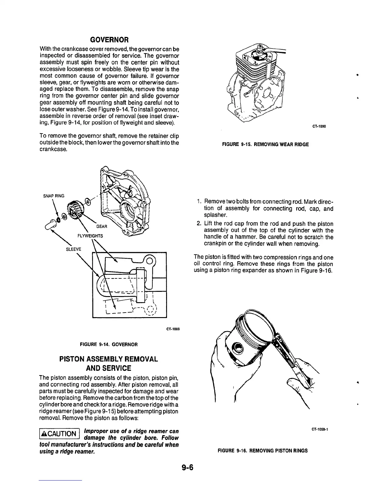
before replacing. Remove the carbon from the top of the
cylinder bore and check for a ridge. Remove ridge with a
ridge reamer (see Figure 9-1
5)
before attempting piston
removal. Remove the piston as follows:
-1
Improper use
of
a
ridge reamer can
damage
fhe
cylinder bore. Follow
fool
manufacfurer's instructions and be careful when
using a ridge reamer.
CT-1059-1
FIGURE
9-16.
REMOVING PISTON
RINGS
9-6

 Loading...
