Carburetor and Intake Manifold
Assembly
Fuel presents the hazard of fire
or
explosion which can cause severe
personalinjury
or
death. Plug fuel lines when servicing
the tuel system
to
prevent fuel leakage.
Do
not permit
any flame, spark, pilot light, cigarette,
or
other ignition
source near the fuel system. Keep an ABC type fire
extinguisher nearby.
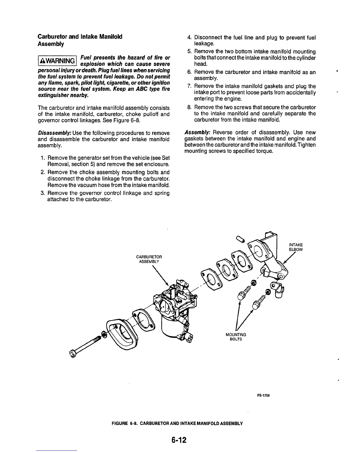
The carburetor and intake manifold assembly consists
of the intake manifold, carburetor, choke pulloff and
governor control linkages. See Figure
6-8.
Disassembly:
Use the following procedures to remove
and disassemble the carburetor and intake manifold
assembly.
Remove the generator set from the vehicle (see Set
Removal, section
5)
and remove the set enclosure.
Remove the choke assembly mounting bolts and
disconnect the choke linkage from the carburetor.
Remove the vacuum hose from the intake manifold.
Remove the governor control linkage and spring
attached
to
the carburetor.
CARBURETOR
ASSEMBLY
4.
Disconnect the fuel line and plug
to
prevent fuel
leakage.
5.
Remove the two bottom intake manifold mounting
bolts that connect the intake manifold to the cylinder
head.
6.
Remove the carburetor and intake manifold as an
assembly.
7.
Remove the intake manifold gaskets and plug the
intake port to prevent loose parts from accidentally
entering the engine.
8.
Remove the two screws that secure the carburetor
to the intake manifold and carefully separate the
carburetor from the intake manifold.
,
Assembly:
Reverse order of disassembly. Use new
gaskets between the intake manifold and engine and
between the carburetor and the intake manifold. Tighten
mounting screws to specified torque.
MOUNTING
BOLTS
FS-1758
FIGURE
6-8.
CARBURETOR
AND INTAKE MANIFOLD ASSEMBLY
6-1
2

 Loading...
