TORQUETO
5-10
IN-LBS
(57
-
1.13
Nom)
RQUE TO
25-30
IN-LBS
(2.8
-
3.4
Nom)
IMPORTANTI THIS
INSULATED
SHUNT
MUST
BE
ROUTED
THRU
UNINSULATED
SHUNT
AS
SHOWN
TO
PRNENT
WITH
COMMUTATOR
IN
FINAL
A
NEGATIVE
BRUSH
__
TERM~NAC
ES-16ll.2
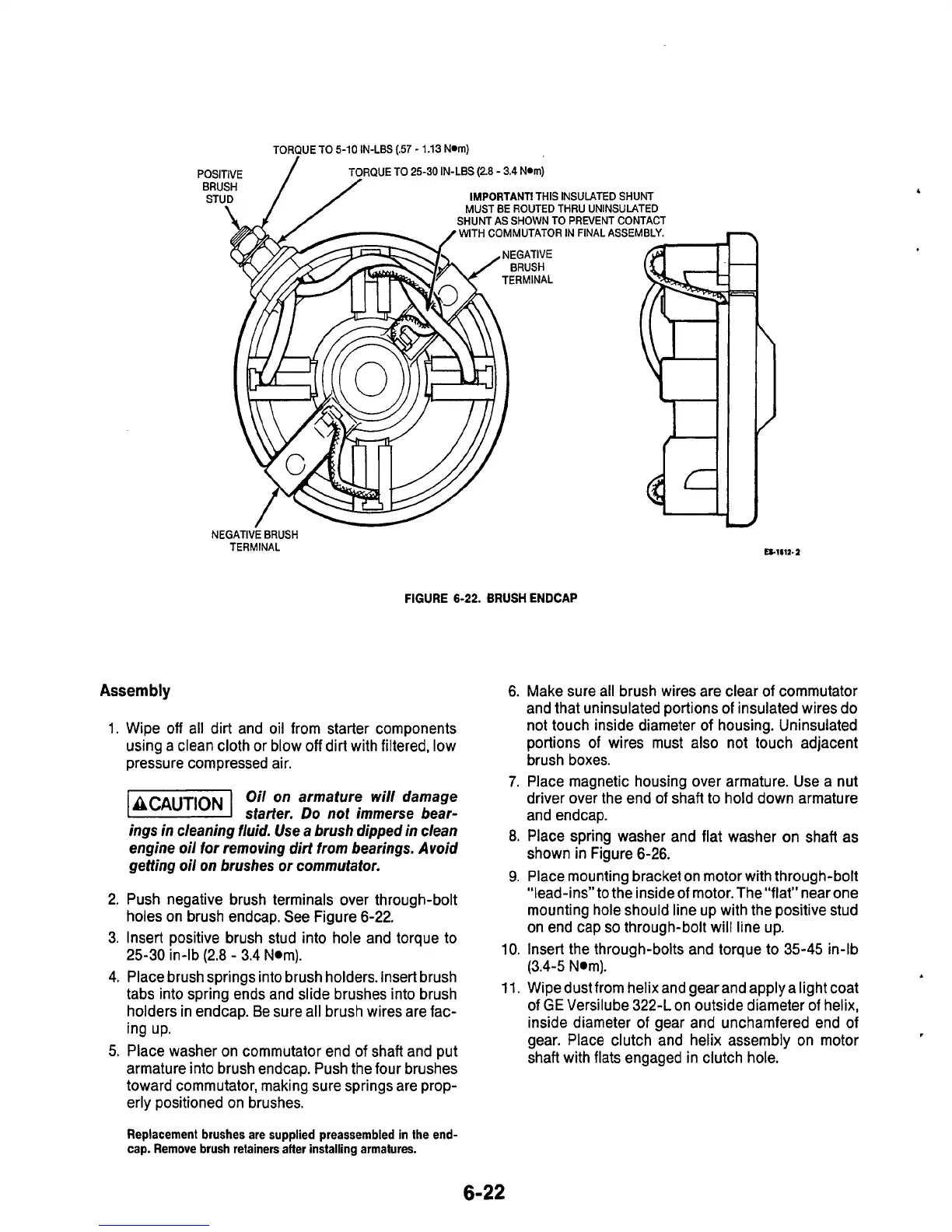
FIGURE
6-22.
BRUSH
ENDCAP
Assembly
6.
Make sure all brush wires are clear
of
commutator
1.
2.
3.
4.
5.
Wipe
off
all dirt and oil from starter components
using a clean cloth or blow
off
dirt with filtered, low
pressure compressed air.
71
Oil
on
armature will damage
*CAUT’oN
starter.
Do
not immerse bear-
ings in cleaning fluid. Use a brush dipped in clean
engine oil
for
removing dirt from bearings. Avoid
getting oil on brushes
or
commutator.
Push negative brush terminals over through-bolt
holes on brush endcap. See Figure 6-22.
Insert positive brush stud into hole and torque to
25-30 in-lb (2.8
-
3.4 Nom).
Place brush springs into brush holders. Insert brush
tabs into spring ends and slide brushes into brush
holders in endcap. Be sure all brush wires are fac-
ing up.
Place washer on commutator end
of
shaft and put
armature into brush endcap. Push the four brushes
toward commutator, making sure springs are prop-
erly positioned on brushes.
Replacement brushes are supplied preassernbled in the end-
cap. Remove brush retainers alter installing armatures.
and that uninsulated portions of insulated wires do
not touch inside diameter
of
housing. Uninsulated
portions of wires must also not touch adjacent
brush boxes.
7.
Place magnetic housing over armature. Use a nut
driver over the end of shaft
to
hold down armature
and endcap.
8.
Place spring washer and flat washer on shaft as
shown in Figure 6-26.
9.
Place mounting bracket on motor with through-bolt
“lead-ins” to the inside of motor.The “flat” near one
mounting hole should line up with the positive stud
on end cap
so
through-bolt will line up.
10.
Insert the through-bolts and torque to 35-45 in-lb
(3.4-5 Nom).
11.
Wipedustfrom
helixandgearandapplyalight
coat
of
GE
Versilube 322-L on outside diameter of helix,
inside diameter of gear and unchamfered end of
gear. Place clutch and helix assembly on motor
shaft with flats engaged in clutch hole.
 Loading...

