11.
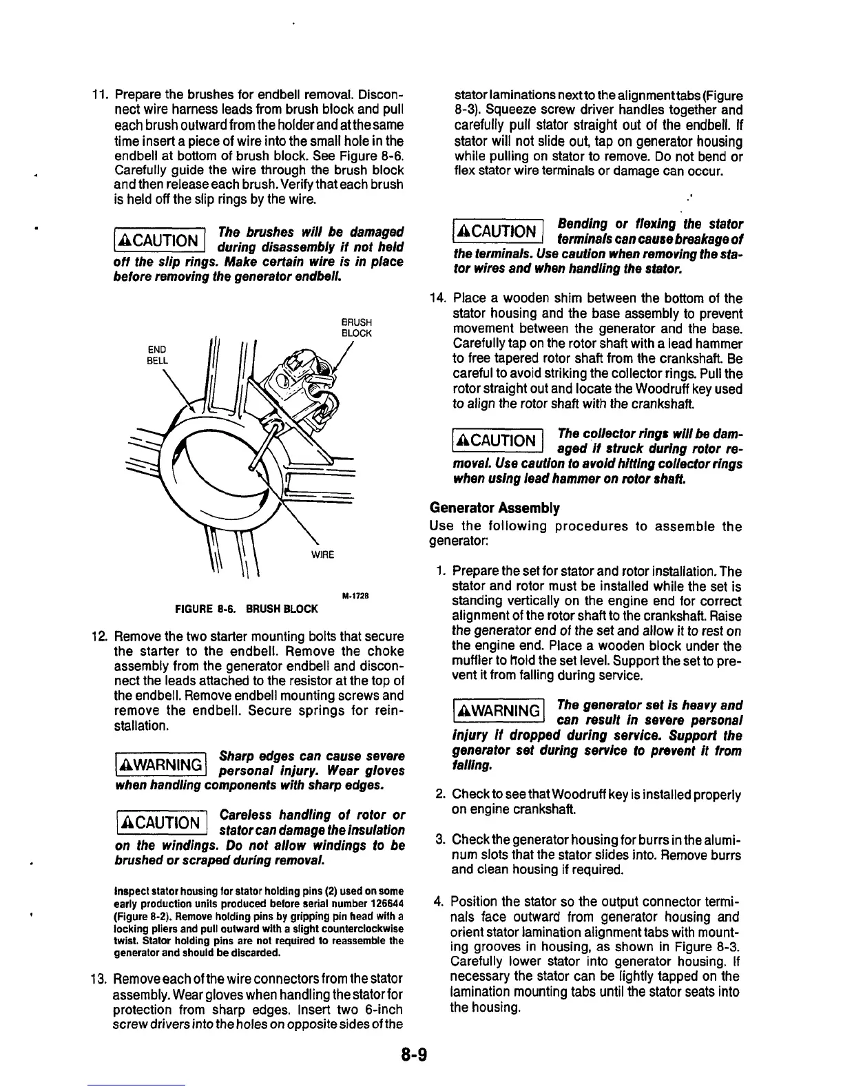
Prepare the brushes for endbell removal. Discon-
stator laminations next to the alignment tabs(Figure
12.
13.
nect wire harness leads from brush block and pull
each
brush
outward from the holder
and
at
the
same
time insert a piece
of
wire into the small hole in the
endbell at bottom of brush block. See Figure
8-6.
Carefully guide the wire through the brush block
and then release each brush. Verify that each brush
is held off the slip rings by the wire.
The brushes will be damaged
(BCAUTIONI
during disassembly
if
not held
off
the slip rings. Make certain wire is in place
before removing the generator endbell.
BRUSH
BLOCK
M-l?ZE
FIGURE
8-6.
BRUSH
BLOCK
Remove the two starter mounting bolts that secure
the starter
to
the endbell. Remove the choke
assembly from the generator endbell and discon-
nect the leads attached to the resistor at the top of
the endbell. Remove endbell mounting screws and
remove the endbell. Secure springs for rein-
stallation.
Sharp edges can cause severe
(BWARNINGI
personal injury. Wear gloves
when handling components with sharp edges.
Careless handling of rotor or
stator can damage the insulation
on the windings.
Do
not allow windings
to
be
brushed or scraped during removal.
Inspect stator housing for stator holding pins
(2)
used on some
early production unils produced before serial number
126644
(Figure
8-2).
Remove holding pins by gripping pin head with a
locking pliers and pull outward with a slight counterclockwise
twist. Stator holding pins are not required to reassemble the
generator and should be discarded.
Remove each
of
the wire connectors from the stator
assembly. Wear gloves when handling the stator for
protection from sharp edges. Insert two 6-inch
screw drivers into the holes
on
oppositesides of the
8-
8-3).
Squeeze screw driver handles togetherand
carefully
pull
stator straight
out
of
the
endbell.
If
stator will not slide out, tap on generator housing
while pulling on stator to remove.
Do
not bend or
flex stator wire terminals or damage can occur.
Bending or flexing the stator
terminals can cause breakage
of
the terminals. Use caution when removing the sta-
tor wires and when handling the stator.
14.
Place a wooden shim between the bottom
of
the
stator housing and the base assembly to prevent
movement between the generator and the base.
Carefully tap on the rotor shaft with a lead hammer
to free tapered rotor shaft from the crankshaft. Be
careful to avoid striking the collector rings. Pull the
rotor straight out and locate the Woodruff key used
to
align the rotor shaft with the crankshaft
The collector rings will
be
dam-
-
aged
If
struck during rotor re-
moval. Use caution to avoid hitting collector rings
when using lead hammer on rotor shaft.
Generator
Assembly
Use
the following procedures to assemble the
generator:
1.
Prepare the set for stator and rotor installation. The
stator and rotor must be installed while the sei is
standing vertically on the engine end for correct
alignment of the rotor shaft to the crankshaft. Raise
the generator end
of
the set and allow it to rest on
the engine end. Place a wooden block under the
muffler
to
hold the set level. Support the set to pre-
vent it from falling during service.
AWARN~NG
The generator set
is
heavy and
I
can result in severe personal
Injury
it
dropped during service. Support the
generator set during service to prevent
it
from
falling.
2.
Check to see that Woodruff key is installed properly
on engine crankshaft.
3.
Check the generator housing for burrs in the alumi-
num
slots
that the stator slides into. Remove burrs
and clean housing if required.
4.
Position the stator
so
the output connector termi-
nals face outward from generator housing and
orient stator lamination alignment tabs with mount-
ing grooves in housing, as shown in Figure
8-3.
Carefully lower stator into generator housing.
If
necessary the stator can be lightly tapped on the
lamination mounting tabs until the stator seats into
the housing.
 Loading...

