Stator
Test
The stator can betested for grounded or open windings
using an ohmmeter. Testing for shorted windings
requires a digital type ohmmeter that can read to within
0.01 ohms.
Figure 8-1
2
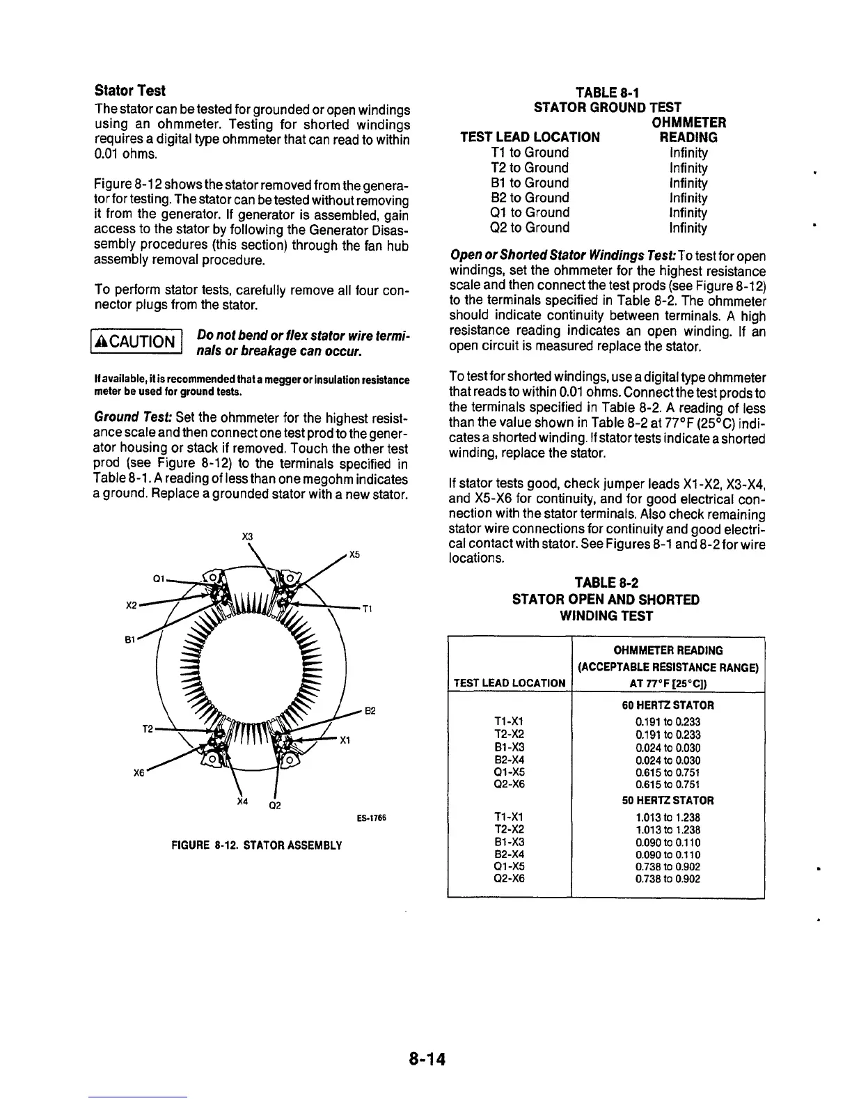
shows thestator removed from thegenera-
tor
for testing. The stator can be tested without removing
it from the generator.
If
generator is assembled, gain
access
to
the stator by following the Generator Disas-
sembly procedures (this section) through the fan hub
assembly removal procedure.
To perform stator tests, carefully remove all four con-
nector plugs from the stator.
Do
not bend or flex stator
wire
iermi-
ISEEEI
na/s
or
breakage can
occur.
If
available, it
is
recommended that a rnegger
or
insulation resistance
meter
be
used for ground tests.
Ground Test:
Set the ohmmeter for the highest resist-
ance scale and then connect one test prod to the gener-
ator housing or stack
if
removed. Touch the other test
prod (see Figure 8-12)
to
the terminals specified in
Table 8-1. A reading
of
less than one megohm indicates
a ground. Replace a grounded stator with a new stator.
B1'
x3
\
X6
x4
a2
ES-1766
FIGURE
8-12.
STATOR ASSEMBLY
TABLE
8-1
STATOR GROUND TEST
OHMMETER
TEST LEAD LOCATION READING
T1
toGround Infinity
T2 to Ground Infinity
B1 to Ground Infinity
Infinity
B2
to Ground
Q1 toGround Infinity
Q2 to Ground Infinity
Open
or
Shorted Stator Windings Test:To
test for open
windings, set the ohmmeter for the highest resistance
scale and then connect the test prods (see Figure 8-12)
to the terminals specified in Table 8-2. The ohmmeter
should indicate continuity between terminals.
A
high
resistance reading indicates an open winding.
If
an
open circuit is measured replace the stator.
To test for shorted windings, use a digital type ohmmeter
that reads to within 0.01 ohms. Connect the test prods to
the terminals specified in Table 8-2. A reading of less
than the value shown in Table 8-2 at 77OF (25OC) indi-
cates a shorted winding.
If
stator tests indicatea shorted
winding, replace the stator.
If
stator tests good, check jumper leads
XI
-X2, X3-X4,
and X5-X6 for continuity, and for good electrical con-
nection with the stator terminals. Also check remaining
stator wire connections for continuity and good electri-
cal contact with stator. See Figures 8-1 and 8-2for wire
locations.
TABLE
8-2
STATOR OPEN AND SHORTED
WINDING TEST
'EST LEAD LOCATION
T1 -X1
T2-X2
B1 -X3
B2-X4
Q1 -X5
Q2-X6
T1
-X1
T2-X2
B1 -X3
B2-X4
Q1 -X5
Q2-X6
OHMMETER READING
ACCEPTABLE RESISTANCE RANGE)
AT
77OF
[25'C])
60
HERTZ STATOR
0.191
to
0.233
0.191
to
0.233
0.024
to
0.030
0.024
to
0.030
0.61
5
to
0.751
0.615
to
0.751
50
HERTZ STATOR
1.01
3
to
1.238
1.01 3
to
1.238
0.090
to
0.1 10
0.090
to
0.1 10
0.738
to
0.902
0.738
to
0.902
.
8-1
4

 Loading...
