7
User Manual
Dolphin Fluid Immersion Simulation
®
System
Dolphin Fluid Immersion Simulation
®
is a registered trademark of Joerns
Keyboard Functions
Warning: For important precautions, see page two.
Caution: The patient’s head should be positioned in
the center of the top section of the therapy mattress.
When using the therapy mattress system, always
ensure that the patient is positioned properly within
the connes of the bed. Do not let any extremities
protrude over the side or between the bed rails when
the therapy mattress is being used.
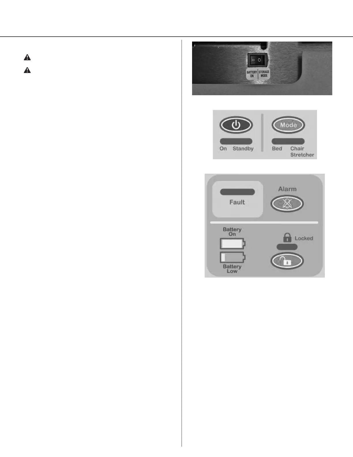
Storage Switch (Figure 2)
The Storage Switch is located on the bottom of the
control unit by the power cord. Turn the Storage
Switch to Battery On for normal operation of the
control unit and to insure the battery charges when
connected to AC power. Turn the Storage Switch to
Storage Mode when the control unit will not be in
use.
Power Button (Figure 3)
Use the Power button to turn the power on and off.
Mode (Figure 3)
In the Bed position, the system operates normally,
but when switched to the Chair/Stretcher position,
the timing cycles change to allow use on a specialty
surface.
Using the specialty surface allows the system to be
moved from the patient bed to a wheelchair cushion
or stretcher pad, providing the normal functions of
the system.
Alarm (Figure 4)
The warning or alarm subsystem consists of LED’s
and a beeper which displays red and beeps when a
fault condition occurs.
A fault condition is considered to be any of the
following conditions:
• Pressure too hard for more than a 10 second
period
• Pressure too soft for more than a 30 minute
period
• Differential error between “Comfort Adjust
setting” and “Auto Feedback” for more than a 30
minute period
The beeper may be manually disabled for up to 30
minutes by pressing the yellow Alarm button.
This feature avoids annoyance while a fault is being
corrected, but will automatically re-assert itself after
30 minutes time, or until the fault is corrected. The
LED’s continue to function normally, regardless of the
Alarm on/off state.
Figure 3
Figure 4
Lock (Figure 4)
The Lock button and associated yellow LED permit
the entire control panel to be locked from further
adjustments.
When locked, pressing the Lock button again
restores normal operation and the yellow LED is
extinguished.
Battery Indicators (Figure 4)
The Battery indicator will blink when the AC power
has been interrupted and the control unit is running
on the battery back-up power.
The Battery Low indicator will blink when the battery
back-up is at the end of its charge life. Plug control
unit back into a power outlet as soon as possible to
resume normal operation. Upon restoration of AC
power, the battery back-up will begin the recharge
process. Note: To ensure the battery recharges
when connected to AC power, the Storage Switch
must be in the Battery On position.
Figure 2