1500 North Belcher Road, Clearwater, FL 33765 • Tel (727) 447-6140 • Fax (727) 442-5699 • sales@onicon.com
Turbine Flow Meter Manual 05/13 - 0721-1 / 13518 Page 16
3.4 INSTALLING THE INSERTION METER
Begin by calculating the effort that will be required to hold the meter. Establish adequate footing for
this task, taking extra caution when working from a ladder or platform. Use the following formula:
E=0.11xP Where: E = effort in pounds
P = system pressure in pounds per square inch
Example: In a 300 PSI system, 33 pounds of effort is required to insert the meter into the pipe.
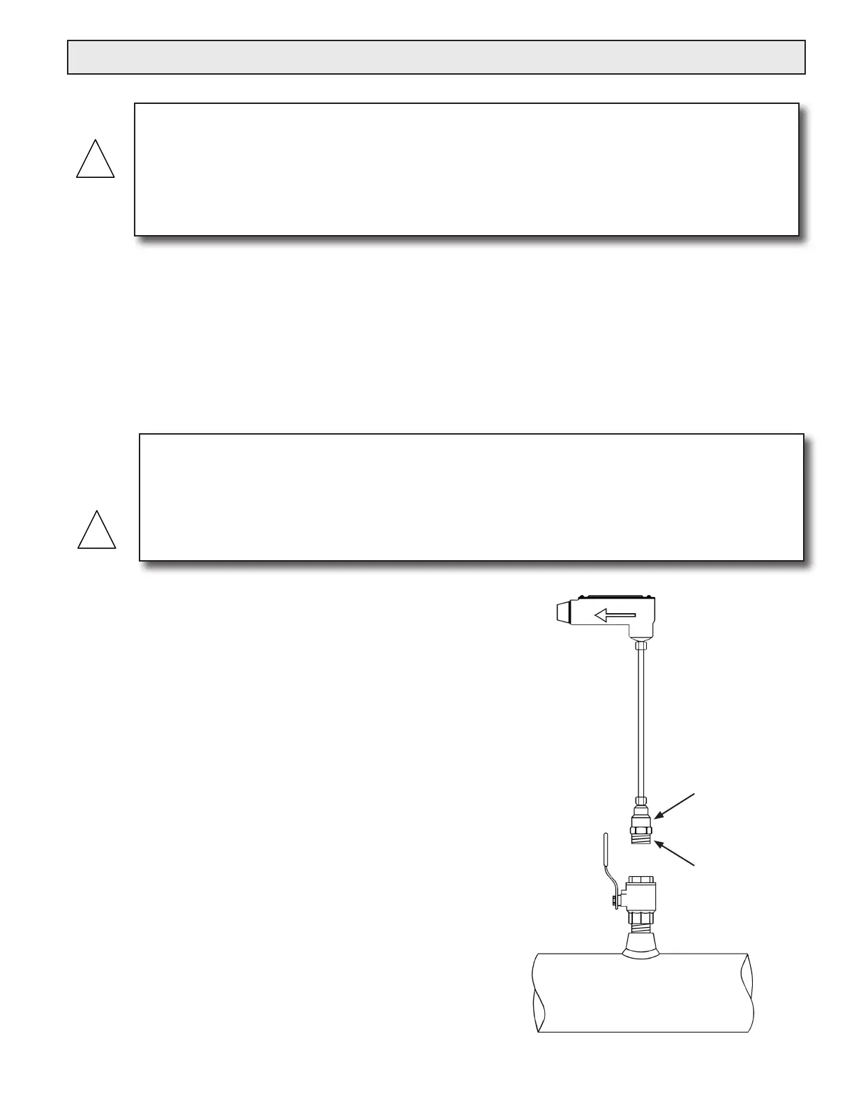
Installing the meter with a factory supplied depth gage:
After tting the necessary plumbing hardware, ush the
entire system so that it is free of ux, solder and slag.
Prepare to install the ow meter by loosening the clamping
nut and withdrawing the turbine assembly fully into the
hot tap adapter. Next, thread the adapter on to the ball
valve using a paste type thread sealant. Do not use Teon
tape as torn strands of the tape may wind around the
turbine, slowing down or even stopping the turbine.
Check the installation for leaks by slightly opening the
ball valve. An ‘O’ ring in the adapter seals the meter
stem against leakage. If there are any leaks around the
clamping nut or stem, DO NOT ATTEMPT TO STOP THE
LEAKAGE BY OVERTIGHTENING THE CLAMPING
NUT. Damage to this nut or the clamping ring under the
nut may prevent the assembly from properly holding
the meter in the pipe. The clamping nut is not part of the
sealing mechanism. Any leaks in this area indicate that the
‘O’ ring is not sealing properly and you must contact the
factory for assistance.
WARNING
When you are ready to rell the system, make sure that all lines are lled with water before inserting
the turbine assembly into the stream. If the lines are not lled, air may interrupt the owing stream
and damage the turbine assembly. A greater danger is that if this is a hot water system, some water
may ash into steam and exceed the high temperature limit for the turbine and its mechanical
assembly. This ash over could exceed the pressure ratings of the meter and the assembly could fail
allowing steam and hot water to escape causing serious injury.
WARNING
SYSTEM MAY BE UNDER HIGH PRESSURE. When installing the meter, adjusting its position
or removing the meter, be sure to hold the electronics enclosure rmly by hand before SLOWLY
loosening the positioning clamping nut. Failure to do this will allow the pressure to suddenly and
rapidly force the meter from the pipe causing serious injury. The meter could also be damaged or
break apart causing a break in the water seal with the resultant loss of large amounts of water. The
hand effort required to hold the meter will be 0.11 times the pipe pressure.
Hot Tap
Adapter
Apply Paste
Type Sealant
to Threads
 Loading...


