1918
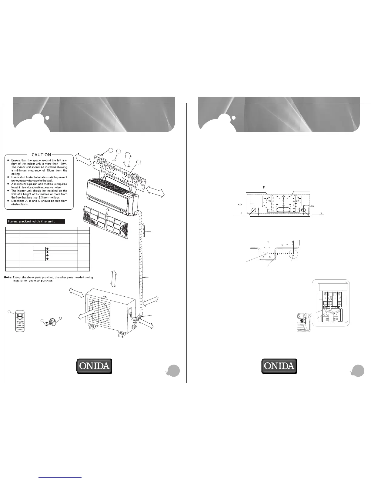
INSTALLATION SKETCH
Number
1
2
3
4
5
6
7
8
9
Name of Accessories
Installation Plate
Clip Anchor
Self-tapping Screw A ST3.9X25
Seal
Drain Joint
Liquid Side
Gas Side
Liquid Side
Gas Side
6.35(12000Btu/h)
12.7(12000Btu/h)
9.53(18000Btu/h)
16.0(18000Btu/h)
Remote Controller
Self-tapping Screw B ST3.9X10
Remote Controller Holder
Q’ty
1
8
8
1
1
1
2
1
Connecting
Pipe
Assembly
Parts You
Must
Purchase
Mounting screw B
ST2.9x10-C-H
Remote controller
holder
8
9
Remote
Controller
7
ADJUST
AUTO
COOL
DRY
HEAT
HEALTH
HIGH
MED
LOW
MODE
FANSPEED
SWING
TIMERON
SLEEP
ON/OFF
TIMEROFF
AUTO
CLEAN
RESETLOCK
SETTEMPERATURE( C)
FOLLOW
ME
LED
DISPLAY
CLEAR
AIR
TURBO
15cm right
15cm left
15cm
above
1
2
3
Loop the
connective
cable.
C
A
60cmabove
60cm above
30cmabove
Air
Filter
Air
Filter
Air
Outlet
30cmabove
Wrapping tape
B
200cmabove
Additional drain pipe
INSTALLATION
n Drill on the wall
Confirm the position of holes and drill holes of diameter 65 mm on the wall
n INDOOR UNIT
1. Fitment of mounting plate
The mounting plate should be fitted on the structural part of wall on which indoor unit
is to be installed.
2. Drill two holes at a distance of 450 mm between them for the expansion bolts.
n Connecting of cables
1. Open the front panel
2. Dismantle the electric box cover
and fastener
3. Connect the cable
4. Reassemble the fastener and electric box
cover.
150mm or more to ceiling
Indoor unit outline
Installation plate
293
Right rear side
refrigerant
pipe hole 65
Left rear side
refrigerant
pipe hole 65
120mm or more
to wall
120mm or more
to wall
995
45
90
45
45
Blue
Terminal board
Power connection wire
Black
Yellow-green
18
10
Center of Hole(Ø65mm)
Insert Ruler
180mm
Align Ruler with straight line