A-8700
ADJUSTMENT
PROCEDURES
Adjustments and Checking the Protection Circuitry
I.
Preparations
I)
Place
the
unit
on
the
workbench.
(There
should
be
about
15
mm
of
space
between
the
base
plate
of
the
unit
and
the
work
surface.)
2) Set up
the
unit as follows.
(I)
No load
(2) No signal
(3)
Volume
turned
all
the
way
down
(4)
Speaker
switch
OFF
(5)
Power
switch
OFF
Note)
Check
the
following points
before
making
adjustments
(I)
The
power
switch
should
be
OFF.
(2)
The
interior
of
the
unit should
not
be
warm
.
2. Idling current adjustment
1)
Turn
the
power
switch
ON
and
allow
the
unit
to
warm up for
about
10
minutes.
(1) Adjust R535 (R635) so
that
the
voltage at test point
VCT-IID
on
the
NAAF-3601 circuit
board
is
15m V
±Sm
V.
Note)
Semi-fixed resistors enclosed in
par
entheses ( )
are
for
the
right channel.
3. Check
of
operation
of
protection circuitry
I)
Check
of
operation
of
protection
relay
(I)
Confirm
that
the
relay turns
ON
approximately
5 seconds
after
the
power
switch
is
turned
ON
.
(2)
The
SERVO
indicator
LED
should
light
at
the
same
time.
(3)
The
relay
should
turn
OFF
approximately
0.5 seconds
after
the
power
switch
is
turned
OFF
.
2)
Check
of
DC
detection
and
servo circuitry
operation
(1)
Turn
the
power
on
with no load.
(2)
After
the
speaker
relay
turns
ON,
apply
DC+
200mV
to
the
CD
input terminals.
Confirm
that
the
relay turns
OFF
.
(3) Confirm
that
operation
is
the
same
as (2)
above
when an
input
of
DC-200mV
is
applied.
Note)
Under
no circumstances
connect
a load
or
short
the
speaker
terminals when
performing
the above test.
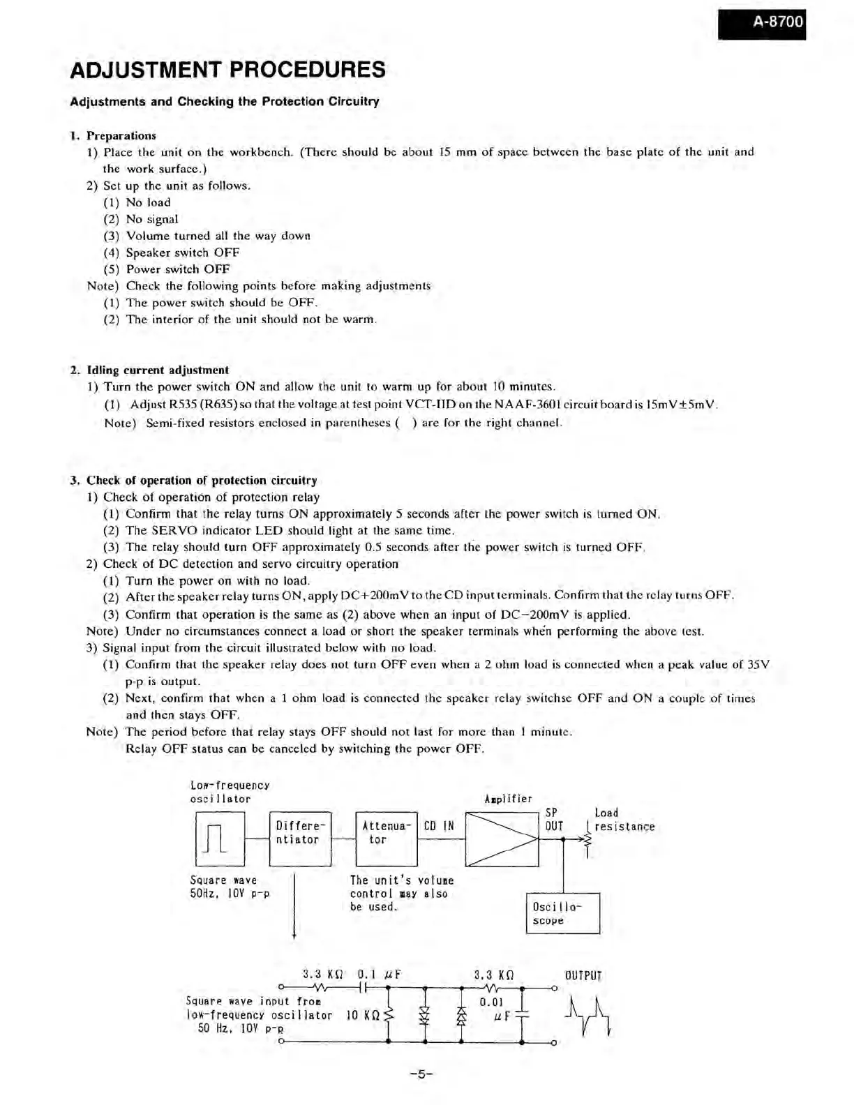
3) Signal input from
the
circuit illustrated below with
no
load.
(I)
Confirm
that
the
speaker
relay
does
not
turn
OFF
even when a 2
ohm
load
is
connected
when a p
ea
k value
of
35V
p-p
is
output.
(2)
Next,
confirm
that
when a 1
ohm
load
is
connected
the
speaker
relay switchse
OFF
and
ON
a couple
of
times
and
then
stays
OFF.
Note)
The
period
before
that
relay stays
OFF
should
not
last for
more
than
1 minute.
Relay
OFF
status can be
canceled
by switching the
power
OFF.
Low-frequency
osc
i I la tor
Jl
Square
wave
50Hz,
I
0V
p-p
Differe-
ntiator
Attenua-
CD
IN
tor
The
unit's
volume
control
■
aY
also
be
used.
3.3
KO
0.1
µf
Amplifier
~---~
SP
Load
3.3
KO
::>¼--0-UT--
➔
-f
resistance
Osc
i
11
o-
scope
OUTPUT
o--;\/v---j
r------.---..--...,·v1r----it-----O
Square
wave
input
from
0.01
~A
lo~
·-
frequencyoscillator
IOKO µF
J\
50
Hz,
l0V
p-P.
-5-
 Loading...