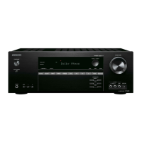
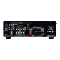
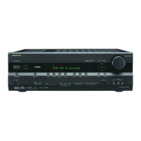
TX-SR402/8240/HT-R420
21
22
No.
1
2
3
4
5
6
7
8
9
10
11
12
13
14
15
16
17
18
19
20
O
-
-
O
I
I
-
-
-
O
O
I/O
I/O
O
I
I
I
O
O
O
I
I
I/O
I
I
I
I
O
OVF
AVSS
AVDD
Pin Name
XTO
XTI
EXTCLK
DVDD
DVSS
TVDD
TX
MCKO
LRCK
BICK
SDTO
SDTI1
SDTI2
SDTI3
INT0
INT1
CDTO
CAD1
CDTI
SDA
CCLK
SCL
CSN
CAD0
DZF2
Analog Input Overflow Detect Pin
This pin goes to "H" if the analog input
of Lch or Rch is overflows.
Analog Ground Pin, 0V
Analog Power Supply Pin, 4.5V 5.5V
FunctionI/O
X'tal Output Pin
X'tal Input Pin
External Master Clock Input Pin
Digital Power Supply Pin, 4.5V 5.5V
Digital Ground Pin, 0V
Output Buffer Power Supply Pin, 2.7V 5.5V
Transmit channel (through data) Output Pin
Master Clock Output Pin
Input/Output Channel Clock Pin
Audio Serial Data Clock Pin
Audio Serial Data Output Pin
DAC1 Audio Serial Data Input Pin
DAC2 Audio Serial Data Input Pin
DAC3 Audio Serial Data Input Pin
Interrupt 0 pin
Interrupt 1 pin
Control Data Output Pin in 4-wire serial
control mode
Chip Address 1 Pin in I
2
C bus control mode
Control Data Input Pin in 4-wire serial
control mode
Control Data Input/Output Pin in I
2
C bus
control mode
Control Data Clock Pin in 4-wire serial
control mode
Control Data Clock Pin in I
2
C bus control
mode
Chip Select Pin in 4-wire serial control mode
Chip Address 0 Pin in I
2
C bus control mode
Zero Input Detect 2 Pin
When the input data of the group 1
follow total 8192 LRCKcycles with
"0" input data, this pin goes to "H".
31
32
33
34
35
36
No.
O
I
I
-
-
-
ROUT1
LIN
RIN
PVDD
R
PVSS
Pin Name
DAC1 Rch Analog Output Pin
Lch Analog Input Pin
Rch Analog Input Pin
PLL Power Supply Pin, 4.5V 5.5V
External Resistor Pin
18k +/-1% resistor to PVSS externally.
PLL Ground Pin, 0V
37 IRX4
Receiver Channel 4 Pin (Internal biased pin)
38 ISLAVE
Slave Mode Pin
"L": Master mode or Slave mode, "H":
Slave mode
39 IRX3
Receiver Channel 3 Pin (Internal biased pin)
40
I
TST
Test Pin
This pin should be connected to DVSS.
41 IRX2
Receiver Channel 2 Pin (Internal biased pin)
42 II2C
Control Mode Select Pin "L": 4-wire
Serial, "H": I2C Bus
43 IRX1
Receiver Channel 1 Pin (Internal biased pin)
44
I
PDN
Power-Down & Reset Pin
When "L ", the AK4586 is powered-down,
all output pins go to "L" and the control
registers are reset to default state. If the
state of CAD1-0 changes, then the
AK4586must be reset by PDN.
FunctionI/O
23
24
25
26
27
28
29
30
I
O
O
O
O
O
O
O
VREFH
VCOM
DZF1
LOUT3
ROUT3
LOUT2
ROUT2
LOUT1
Positive Voltage Reference Input Pin, AVDD
Common Voltage Output Pin, AVDD/2
Large external capacitor around 2.2
F is used to reduce power-supply noise.
Zero Input Detect 1 Pin
When the input data of the group 1
follow total 8192 LRCK cycles with
"0" input data,this pin goes to "H".
DAC3 Lch Analog Output Pin
DAC3 Rch Analog Output Pin
DAC2 Lch Analog Output Pin
DAC2 Rch Analog Output Pin
DAC1 Lch Analog Output Pin
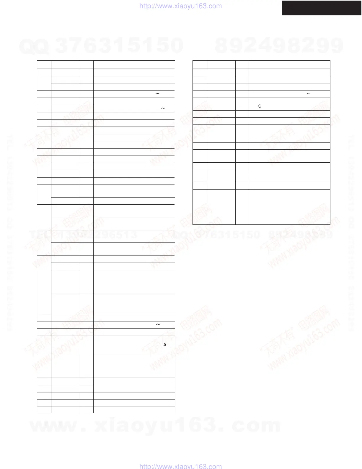
IC BLOCK DIAGRAM AND TERMINAL DESCRIPTIONS-7
Q801: AK4586 (24-Bit 96kHz 6-channel CODEC with DIR)-2
TERMINAL DESCRIPTION
w
w
w
.
x
i
a
o
y
u
1
6
3
.
c
o
m
Q
Q
3
7
6
3
1
5
1
5
0
9
9
2
8
9
4
2
9
8
T
E
L
1
3
9
4
2
2
9
6
5
1
3
9
9
2
8
9
4
2
9
8
0
5
1
5
1
3
6
7
3
Q
Q
TEL 13942296513 QQ 376315150 892498299
TEL 13942296513 QQ 376315150 892498299
http://www.xiaoyu163.com
http://www.xiaoyu163.com
 Loading...