Do you have a question about the Onkyo HT-R380 and is the answer not in the manual?
Checks power supply and MPU board voltages for no power condition.
Recommends replacing power supply or repairing the sub transformer circuit.
Suggests specific part replacements for faults.
Addresses display tube or board replacement for no display.
Inspects signal lines for damage to resolve display issues.
Analyzes HDMI board waveforms for no sound from HDMI.
Evaluates AF board resistance for sound troubleshooting.
Checks video board AC voltage for no picture faults.
Verifies HDMI board voltage for no picture issues.
Block diagram of the HDMI board for video/audio.
Block diagram of the MPU, DIR, and DAC board.
Details components in the MPU section and thermal sensor.
Outlines valid firmware version combinations.
Guide for verifying firmware versions on the monitor.
Instructions for preparing the PC and connections for firmware updates.
Visual guide for connecting devices for firmware updates.
Step-by-step instructions for updating firmware.
Details playback for PC/CD firmware update files.
Exploded view identifying parts specific to various models.
Shows wiring between display, amp, and MPU/DAC boards.
Wiring diagram for video, HDMI, and U-PORT sections.
Schematic for tuner pack and analog audio inputs.
Schematic for optical digital audio input.
Video block section schematic for the Japan model.
Schematic for component video input/output.
Schematic of amplifier IC/ASP board audio input section.
Schematic of the amplifier IC/ASP board power section.
Schematic for the MPU, DAC, and DIR boards.
Schematic of the video PC board for different models.
Schematic for the U. Port PC board.
Schematic for the display PC board.
Schematic for the standby key/LED PC board.
Schematic of the power supply board.
Schematic for the HDMI transceiver PC board.
Schematic for the HDMI DSP PC board.
Component layout of the amplifier PC board (A-side).
Component layout of the FL Tube/VP PC board (A-side).
Soldering layout of the amplifier PC board (B-side).
Soldering layout of the FL Tube/VP PC board (B-side).
Component layout of the MPU/DAC PC board (A-side).
Component layout of the U. Port PC board (A-side).
Component layout of the display PC board (A-side).
Component layout of the standby key/LED PC board (A-side).
Soldering layout of the display PC board (B-side).
Soldering layout of the video PC board (B-side).
Component layout of the HDMI PC board (A-side).
Soldering layout of the HDMI PC board (B-side).
List of transformer coil parts in the exploded view.
List of semiconductor parts in the exploded view.
List of packing materials.
List of accessory items.
List of parts for tuner unit PC boards.
List of semiconductor parts for PC boards.
Detailed list of semiconductor components.
Details on switch terminal components like screws and retainers.
List of diodes and LEDs in the semiconductor section.
List of diodes and ICs in the semiconductor section.
List of inductors and coils for transformer sections.
List of carbon resistors and their values.
List of wire traps and plugs for switch terminals.
| Channels | 5.1 |
|---|---|
| HDMI Inputs | 4 |
| HDMI Outputs | 1 |
| Weight | 17.6 lbs |
| Response Bandwidth | 10 Hz - 100 kHz |
| THD | 0.08% |
| Input Impedance | 47 kOhm |
| Input Sensitivity | 200 mV |
| Tuner Bands | AM/FM |
| Surround System Class | 5.1 channel |
| Digital Sound Processor (DSP) | Yes |
| HDMI Switching | Yes |
| Bluetooth | No |
| HDMI Version | 1.4a |
| Power Output | 100W per channel (6 ohms, 1 kHz, 1% THD, 1 channel driven) |
| Dolby Technologies | Dolby Digital, Dolby Digital Plus, Dolby TrueHD |
| DTS Technologies | DTS, DTS-HD Master Audio |
| DSP Presets | Game, Movie, Music |
| Input Video Formats | HDMI |
| Audio D/A Converter | 24bit / 192kHz |
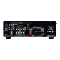
| Inputs | HDMI, Composite, Optical, Coaxial |
| Outputs | HDMI, Composite |