Do you have a question about the Onkyo HT-R320 and is the answer not in the manual?
Details on audio, tuner, power, dimensions, and connectivity specs.
Procedures for fuse replacement, safety checks, and unit initialization.
Steps to check microprocessor version and information on memory backup.
Procedures for testing DC voltage and current protection circuits in test mode.
Explanation of power modes and steps for output/thermal detection checks.
Detailed steps for performing output level and thermal detection tests.
Instructions to enter DSP debug mode and explanation of its display parameters.
Circuit diagrams for interface, video, and headphone jack PC boards.
Circuit diagrams for power supply and speaker terminal PC boards.
Circuit diagrams for regulator and terminal PC boards.
Preparation and procedure for adjusting idling current using test points and resistors.
Component lists for pre-amplifier, driver, interface, and speaker terminal boards.
Component lists for power amplifier, terminal, supply, and other PC boards.
| Channels | 5.1 |
|---|---|
| Audio Formats Supported | Dolby Digital, DTS |
| FM Tuner | Yes |
| Frequency Response | 20 Hz - 50 kHz |
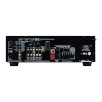
| Digital Audio Inputs | 2 Optical, 1 Coaxial |
| HDMI Outputs | 1 |
| USB Port | No |
| AM Tuner | Yes |
| Tuning Range | FM: 87.5-108 MHz |
| Speaker Load Impedance | 6 Ohms - 16 Ohms |
| Video Connections | Composite, Component |
| Amplifier Type | Discrete |
| Input Sensitivity and Impedance | 200 mV/47 kOhms (Line) |
| Signal-to-Noise Ratio | 100 dB |