EasyManua.ls Logo

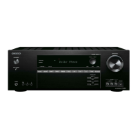
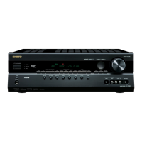
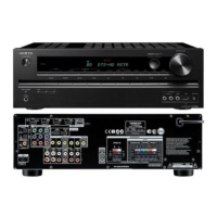
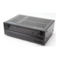
Onkyo HT-R420 Service Manual

Onkyo HT-R420
89 pages
To Next Page IconTo Next Page
Page #1 background imageLoading...
Page #1 background image
TX-SR402/8240/HT-R420
SERVICE MANUAL
AV RECEIVER
MODEL
TX-SR402
TX-SR8240
HT-R420
Ref. No. 3796
032004
TX-SR402
Silver and Golden models
220-230V AC, 50/60HzSMGR,GMGR
HT-R420 Black and Silver models
120V AC, 60HzBMDC,BMDD,SMDC,SMDD
230-240V AC, 50HzBMPA,SMPA,SMPT
120V/220-230V AC, 50HzSMWT
TX-SR8240 Golden models
220-230V AC, 50/60HzGMGR
RC-518M
(Noth American model)
RC-479S
(Other models)
SAFETY-RELATED COMPONENT
WARNING!!
COMPONENTS IDENTIFIED BY MARK ON THE
SCHEMATIC DIAGRAM AND IN THE PARTS LIST ARE
CRITICAL FOR RISK OF FIRE AND ELECTRIC SHOCK.
REPLACE THESE COMPONENTS WITH ONKYO
PARTS WHOSE PART NUMBERS APPEAR AS SHOWN
IN THIS MANUAL.
MAKE LEAKAGE-CURRENT OR RESISTANCE
MEASUREMENTS TO DETERMINE THAT EXPOSED
PARTS ARE ACCEPTABLY INSULATED FROM THE
SUPPLY CIRCUIT BEFORE RETURNING THE
APPLIANCE TO THE CUSTOMER.
w
w
w
.
x
i
a
o
y
u
1
6
3
.
c
o
m
Q
Q
3
7
6
3
1
5
1
5
0
9
9
2
8
9
4
2
9
8
T
E
L
1
3
9
4
2
2
9
6
5
1
3
9
9
2
8
9
4
2
9
8
0
5
1
5
1
3
6
7
3
Q
Q
TEL 13942296513 QQ 376315150 892498299
http://www.xiaoyu163.com

Other manuals for Onkyo HT-R420

Questions and Answers:

Onkyo HT-R420 Specifications

General IconGeneral
Channels5.1
Surround SoundDolby Digital, DTS
Power Output (per channel)100 W
Total Harmonic Distortion0.08%
Inputs4 x HDMI
Outputs1 x HDMI
Tuning rangeFM: 87.5 - 108 MHz, AM: 530 - 1, 710 kHz
Speaker load impedance6 Ohms - 16 Ohms
Video ConnectionsHDMI, Component Video, Composite Video

Summary

Onkyo AV Receiver Specifications

Amplifier Section Specifications

Details power output, distortion, frequency response, and tone control specifications.

General and Tuner Specifications

Covers power supply, dimensions, weight, and FM/AM tuner details.

Service Procedures and Checks

Fuse Replacement and Safety Procedures

Instructions for replacing fuses and performing safety checks on the unit.

Unit Initialization and Microprocessor Settings

Procedures for unit initialization, microprocessor checks, and voltage settings.

Panel Views and Controls

Front Panel Overview and Indicators

Details the functions of buttons, dials, and indicators on the front panel.

Rear Panel Connections

Describes the purpose of each terminal on the rear panel for connectivity.

Remote Controller Description

Explains the functions of buttons on the RC-518M and RC-479S remote controllers.

Technical Diagrams and Schematics

Exploded Views and Block Diagrams

Visual part breakdown and high-level functional overviews of the unit.

Schematic and PC Board Diagrams

Detailed electrical circuit and PC board layout diagrams.

IC Block Diagrams and Terminal Descriptions

Details on integrated circuits, including block diagrams and pinouts.

Adjustment and Operation Checks

Idling Current Adjustment Procedures

Step-by-step guide for adjusting the idling current of the amplifier.

Operation Checks (Protection and DSP)

Procedures for checking protection circuits, output levels, thermal functions, and DSP.

Packing Procedures

Exploded View Parts List

Related product manuals