Do you have a question about the Onkyo HT-R494 and is the answer not in the manual?
Explains the naming convention for Excel parts list files based on model, color, voltage, and destination.
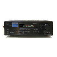
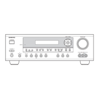
Lists all accessories included with the unit, such as antennas, remote controller, and batteries.
Step-by-step instructions to reset the main unit to its default state.
Instructions for resetting the remote control unit's functionality.
Describes the unit entering standby mode due to abnormal conditions like thermal, DC voltage, or current detection.
Explains the self-diagnostic function for identifying amplifier circuit failures during power-on.
Steps for confirming the protect cause and clearing error information after repairs.
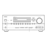
Procedure to check the unit's model name and destination via the front panel display.
Steps to check firmware versions and prepare for firmware updates using MMC storage.
First part of the service mode update: connecting MMC card and powering on the unit.
Second part of the update process: waiting for completion, powering off/on, and checking the new version.
Details on disassembling the front panel components.
Details on disassembling the processor board.
Details on disassembling the amplifier section.
Block diagram illustrating the audio processing path.
Block diagram illustrating the video processing path.
Block diagram illustrating the digital audio processing path.
Schematic of the Amplifier Signal Processor section.
Schematic of the main amplifier stages, including power and driver circuits.
Schematic details of the thermal sensor circuit within the amplifier section.
Schematic details of the voltage amplifier stages in the amplifier section.
Schematic of the primary power supply circuitry.
Schematic of the video signal processing path.
Schematic of the front panel display and control circuits.
Schematic of the headphone jack circuitry.
Schematic of the main microprocessor unit and its connections.
Schematic of the Video Processor Unit's power supply.
Schematic of the video processing integrated circuit.
Schematic for digital audio interface, DAC, and Bluetooth module.
Schematic of the Digital Signal Processor and related circuits.
Schematic of the FM/AM tuner circuitry.
Schematic for the Bluetooth module's connector and interface.
General exploded view showing the main assemblies of the unit.
Exploded view detailing the components of the front panel.
Exploded view of the heat sink assembly and associated power transistors.
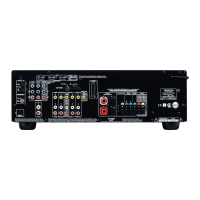
Exploded view detailing the components and connectors on the rear panel.
Diagram illustrating the procedure for packing the unit.
How to access and interpret service information for analyzing unit status.
Procedures for checking unit operations, sensors, and LEDs.
Steps for setting the volume level and clearing data for shipping.
Steps to enter various diagnostic test modes via button combinations.
Procedure to test all buttons and the master volume control in test mode.
Procedure to check the unit's output sensors (low and high detect).
Steps to test the functionality of all segments on the front panel FL display.
Debug mode for analyzing digital audio issues by checking DSP and DIR operations.
Debugging codes related to various source modes.
Debugging codes for external decoder settings.
Debugging codes for external decoder commands.
Debugging codes related to muting ports and factors.
Debug codes for DA830 input/output sample rates, MCLK, and channel info.
Debug codes for DIR and DAC sequences, switch numbers, and DSP/muting info.
Debugging codes indicating audio output status (OK/NG).
Details on formats displayed on the FL screen during debug.
How to enter and interpret the HDMI resolution display mode.
Steps to enter service information mode for analyzing unit status.
Procedure to exit the service information mode and return to normal display.