25
IR IN
MAIN ZONE 2
ZONE 2
OUT
BACK
L
L
R
BACK
R
R
L
CAUTION:SPEAKER IMPEDANCE
6 OHMS MIN. PER EACH
SPEAKER TERMINAL
SURROUND
(
SURR
)
SPEAKERS
AC OUTLETS
AC 120V 60Hz
SWITCHED
TOTAL 120W 1A MAX.
AC
INLET
AM
ANT.
FM
ANT.
75
MULTI
CHANNEL
INPUT
RS232
GND
C
FRONT
AMP
IN
R
L
SURR
BACK
SURR
PRE OUT
SUB
WOOFER
FRONT
SPEAKERS
CENTER
SPEAKER
CAUTION:
SPEAKER IMPEDANCE
6 OHMS MIN. PER EACH
SPEAKER TERMINAL
1
2
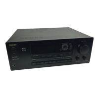
MODEL NO.
TX-DS989
AV RECEIVER
VIDEO
S VIDEO
DVD
VIDEO
5
VIDEO
4
VIDEO
3
MONITOR
OUT
VIDEO
1
VIDEO
2
OUT
IN
IN
IN
IN
IN
IN
OUT
R
L
VIDEO
S VIDEO
C
D
TAPE
2
TAPE
1
I
N
I
N
I
N
I
N
OUT
OUT
L
R
PHONO
3
2
1
3
2
5
4
1
DIGITAL
OUTPUT
(
COAXIAL
)
AC-3
RF
DIGITAL
INPUT
(
COAXIAL
)
DIGITAL
OUTPUT
(
OPTICAL
)
DIGITAL
INPUT
(
OPTICAL
)
INPUT 2
P
B
P
R
Y
INPUT 3
P
B
P
R
Y
OUTPUT
P
B
P
R
Y
COMPONENT
VIDEO
INPUT 1
P
B
P
R
Y
1
2
R
L
IR IN
MAIN ZONE 2
HOME THEATER CONTROLLER
RC-390M
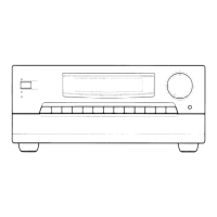
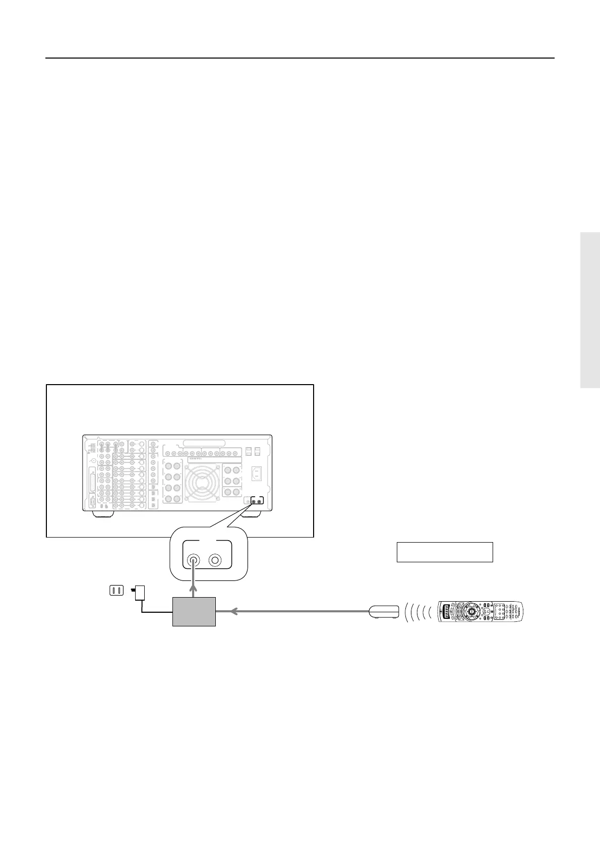
Connecting to the IR IN MAIN input
In the cabinet
Outside of the cabinet
Remote sensor
(Multi-Room System kit)
Remote controller
Connecting block
(Multi-Room System kit)
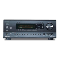
TX-DS989
Outline
If the TX-DS989 is located inside a cabinet or other enclosure
where the infrared beams from the remote controller cannot enter,
then operation with the remote controller will not be possible. In
such a case, it will be necessary to install a remote sensor at a
location outside of the cabinet for the infrared beams from the
controller to reach.
1. Connect the connecting block to the IR IN
MAIN input at the TX-DS989.
2. Install the remote sensor at a location where it
can detect the infrared beams from the remote
controller.
3. Connect the remote sensor to the connecting
block.
Mini plug cable
Power supply
Wall outlet
 Loading...