Do you have a question about the Onkyo TX-DS696 and is the answer not in the manual?
Detailed electrical characteristics of the amplifier's output and input stages.
Detailed specifications for FM and AM tuner sensitivity, selectivity, and performance.
Overall specifications including power supply, consumption, dimensions, and weight.
Instructions for replacing fuses, emphasizing correct type and rating for safety.
Procedure to reset the microprocessor, clearing all preset settings to factory defaults.
Mandatory safety checks, including insulation resistance, before releasing the unit.
Information on the unit's built-in memory backup system for settings.
Guide for changing the AM tuning step frequency for worldwide models.
Instructions for setting the voltage selector to match local power supplies.
Component modification details for changing the AM band tuning step.
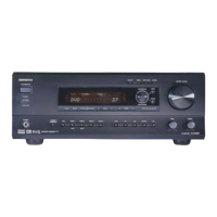
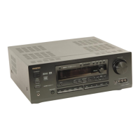
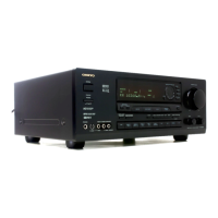
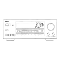
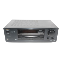
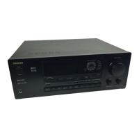
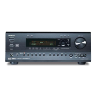
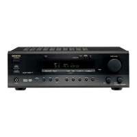
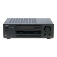
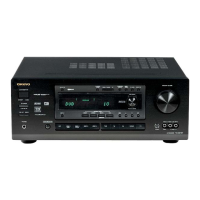
Identification and description of controls, indicators, and connectors on the front panel.
Explanation of the information displayed on the unit's front display.
Description of primary buttons like ON/STDBY, SETUP, and related indicators.
Covers buttons for selecting input sources and listening modes.
Includes volume control, mute, test/menu, and zone functions.
Illustrates the path of audio and video signals through the unit's inputs and outputs.
Guides for connecting various audio, video, and speaker components to the receiver.
Diagram and pinout description for the AK4112AVF digital interface receiver IC.
Detailed list of terminals and their functions for the main microprocessor (MPD703033AGC).
Detailed list of terminals and their functions for the sub microprocessor (UPD70232GC).
Step-by-step guide on how to access and initiate the unit's debug mode.
Interpretation of error messages and status indicators shown in debug mode.
How to interpret results of DSP input signal detection and check signal integrity.
Information on whether the DSP IC is successfully decoding the input digital signal.
Explanation of various segment lighting patterns used for testing the FL tube display.
Details the pin assignments for controlling the FL tube segments.
List of components for the DSP circuit board.
List of components for the Power Amplifier A circuit board.
Illustrates the internal wiring connections between major PCBs and components.
High-level overview of the unit's internal signal paths and functional blocks.
Soldering side view of the input terminal circuit board.
Soldering side view of the tone control circuit board.
Component layouts for power amplifier and regulator circuit boards.
Component layouts for terminal and switch circuit boards.
Component layout for the display circuit board.
Component layout for the volume control circuit board.
Component layout for the headphone terminal circuit board.
Component layout for the S-video terminal circuit board.
Component layout for the composite video circuit board.
Component layout for the component video terminal circuit board.
Component layout for the DSP circuit board.
Detailed schematic of the audio and video input signal processing circuits.
Detailed schematic of the power amplifier stage A circuitry.
Schematic diagram illustrating the operation of the unit's display system.
Schematic diagram of the video signal processing and switching circuits.
Schematic diagram detailing the Digital Signal Processing (DSP) circuitry.
Detailed schematic of the specific DSP circuit components and connections.
Procedure to adjust the amplifier's idling current for optimal performance.
Verifying speaker relay operation for protection against faults.
Checking DC voltage detection functionality for speaker relay control.
Verifying current detection circuit operation for speaker relay control.
Guides for entering test modes and confirming FL tube displays.
Procedures for confirming voltage sensor readings and thermal protection.
Visual breakdown of the unit's components for assembly and disassembly reference.
List of part numbers for various printed circuit boards (PCBs) used in the unit.
List of specific fuses and their corresponding holders with part numbers.
List of various connectors, sockets, plugs, and accessories with part numbers.
Illustration showing the arrangement of the unit and accessories during packing.
List of packing materials, accessories, and printed matter included in the package.