Test Mode
1. Turn POWER button on.
2. Press and hold down DVD button, then press STANDBY button.
3. During "TEST-1" on the FL tube is displayed, press CD button to set the unit to the test mode of FL tube.
Note: VIDEO 1:TEST-1 VIDEO 2 :TEST-2 ZONE2/SP A: UP
VIDEO 3 :TEST-3 VIDEO 4:TEST-4 REC OUT/SP B: DOWN
Test-X YZ
Item
FL TUBE
The segments of even
number light on .
All segments
light on.
"FEDCBA987654321"
light on.
"Good bye XDN EU"
light on.
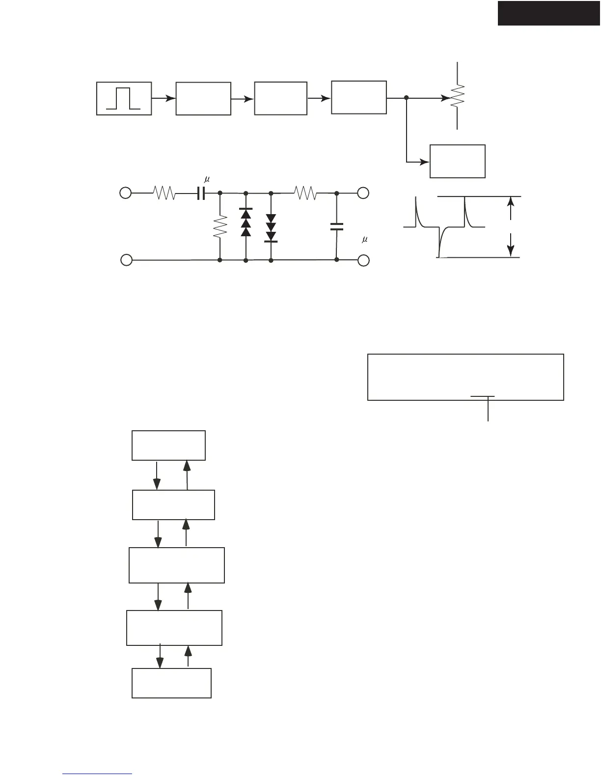
CR
OSCILLATOR
DIFFEREN-
TIATING
CIRCUIT
ATTENU-
ATOR
UNIT
SPEAKER
TERMINAL
MULTI
CHANNEL
INPUT
INPUT
OUT-
PUT
3.3k
10k
1SS133
3.3k
GND
0.01 F
0.1 F
OSCILLO-
SCOPE
Differentiating Circuit
200Hz
SQUARE
Test mode of FL tube
Press ZONE 2 or REC OUT button
to change the test mode of FL tube.
REC OUT
SPEAKER B
ZONE 2
SPEAKER A
Press POWER button
to finish the test mode of FL tube.
XNO EU
1 2 3 4
1. 12V Trigger T: Use
2. Video Mode N: NTSC P: PAL AUTO
3. AM band step 9: 9 kHz step 0:10 kHz step
4. Tuner band EU:Europe US: USA SA:Saudi JP:Japan
The segments of odd
number light on .
35Vp-p
TX-DS595:Press SPEAKER A or SPEAKER B button
to change the test mode of FL tube.
TX-DS696:
Confirmation of voltage sensor
1. Set the unit to TEST-3-4.
2. Apply the signal 1kHz, -15dBV to the MULTI-CH
input. Confirm that the FM STEREO is displayed.
Confirm the all channels except SUBWOFFER.
3. When connect the resistor 1.2 kohm/1 W between
the terminals COM and TH1 of P6401, confirm that
the spaker relays of RL6901 and RL6902 turn off.
Note: No input signal.
4.When change SPEAKER IMPEDANCE switch to 4 ohm,
confirm that the speaker relays of RL6901 and RL6902
turn off.
Note: No input signal.
Confirmation of thermal protect
Set the unit to TEST-1-00 with no input signal.
When connect the resistor 1.2 kohm/1 W between the
both terminals of P6401, confirm that all speaker relays
turn off.
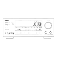
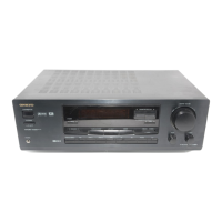
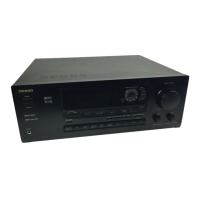
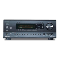
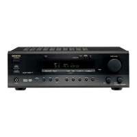
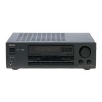
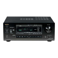
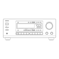
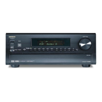
TX-DS595/696