OP5600/OP5650 User Manual OPAL-RT Technologies 16
OP5600 Series/OP5650 Simulator
DB37F Connections
.
channels 16-31
channels 16-31
channels 0-15
channels 0-15
GROUP1B
GROUP 1A
GROUP 1B
GROUP 1A
GROUP 1B
OP5600 Front (RJ45)
OP5600 Rear (DB37)
GROUP 1B
GROUP 1A
DIGITAL MEZZANINES
(top view)
Connector rear view
GROUP1A
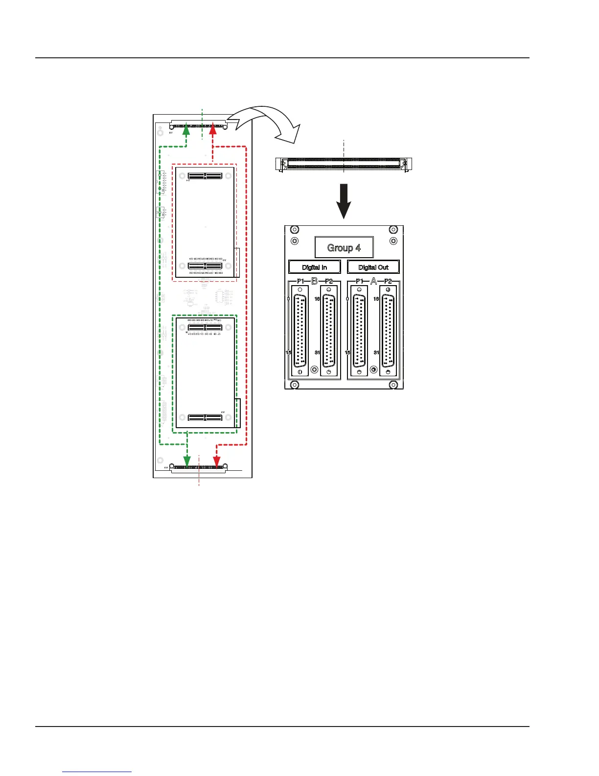
Figure 7: DB37 connection to mezzanines
If the front mezzanine is a digital module (Din or Dout), the first 16 channels (00 to 15) are on the first
connector and the next 16 channels (16 to 31) are on the second connector.
If the back mezzanine is a digital module (Din or Dout), the first 16 channels (00 to 15) are on the first
connector and the next 16 channels (16 to 31) are on the second connector.
All signals are represented by a positive-negative pair that are always available on the connector pins,
for example: for channel 08 : (08+, -08)
INTERFACE:
• For a single-ended output, the negative conductor is connected to Ground.
• For a differential output, the positive and negative signals are on the connector.
• For a differential input, the connection must be between the positive/negative pair.
• If the input is singled-ended, user’s ground must be connected to the negative side of the pair.