OP5600/OP5650 User Manual OPAL-RT Technologies 20
OP5600 Series/OP5650 Simulator
RJ45 channel Assignments
connecting monitoring devices
The OP5650 simulator offers quick, single-ended connections, through RJ45 and mini BNC connectors,
to any monitoring device (i.e. oscilloscope, etc.). These mini-BNC jacks let you monitor 4 channels
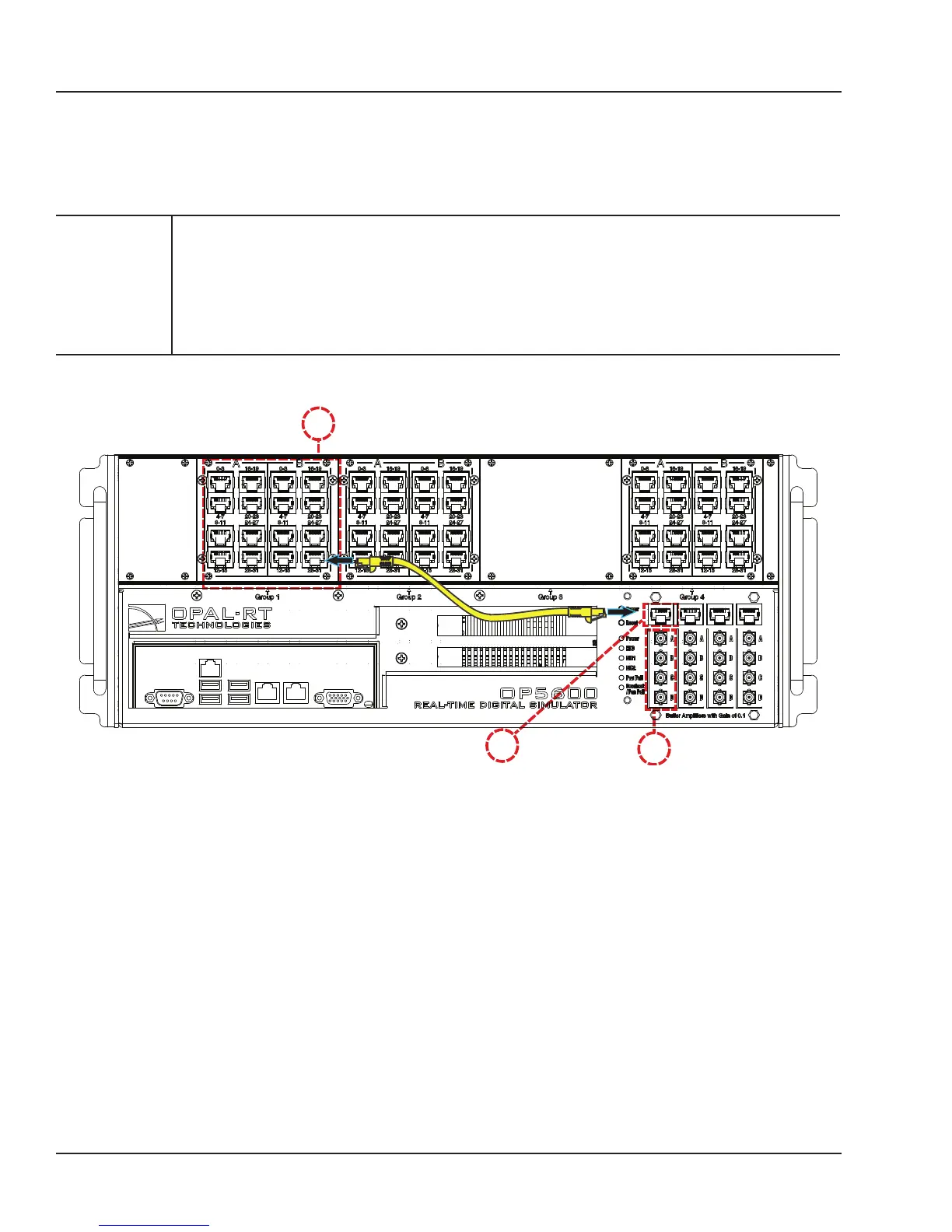
individually. Simply follow these instructions (as illustrated in Figure 12):
CAUTION
Only connect RJ45 cables from upper section (A) monitoring jacks to lower section
monitoring panel (B, as shown). Connecting any other cable or device may result in
damage to the equipment.
The network cable must only be connected to the standard computer connector network
jack (see page 15). DO NOT connect the network cable in any jack other than the jack
intended for that purpose.
A
B
C
Figure 10: How to connect cables for monitoring
1. Connect one end of the RJ45 cable to the desired channels (A). See Figure 11 for RJ45 connector
pinouts
2. Connect the other end of the RJ45 cable to the monitoring connector (B)
3. Connect a mini-BNC cable to each BNC jack (C) and connect the other end of the cable to the
desired monitoring device. The mini-BNC jacks each connect to one of the 4 channels of the RJ45
Connector (A). In the example shown in Figure 8, the RJ45 cable is connected to channels 28-31.
The mini-BNC cable jacks, identified as A, B, C, D, represent each channel in the following order;
A = channel 28,
B = channel 29,
C = channel 30
D = channel 31.