6
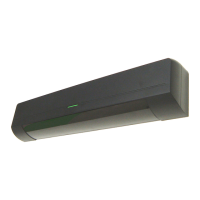
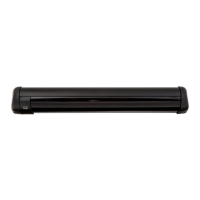
5. AX-350/650TF
Receiver Transmitter
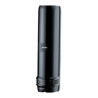
CAUTION : Make sure to connect the jumper (U-shaped connector), when not
using the retransimitting circuit. If the jumper is not connected, the
Transmitter will not transmit beam (Alarm condition).
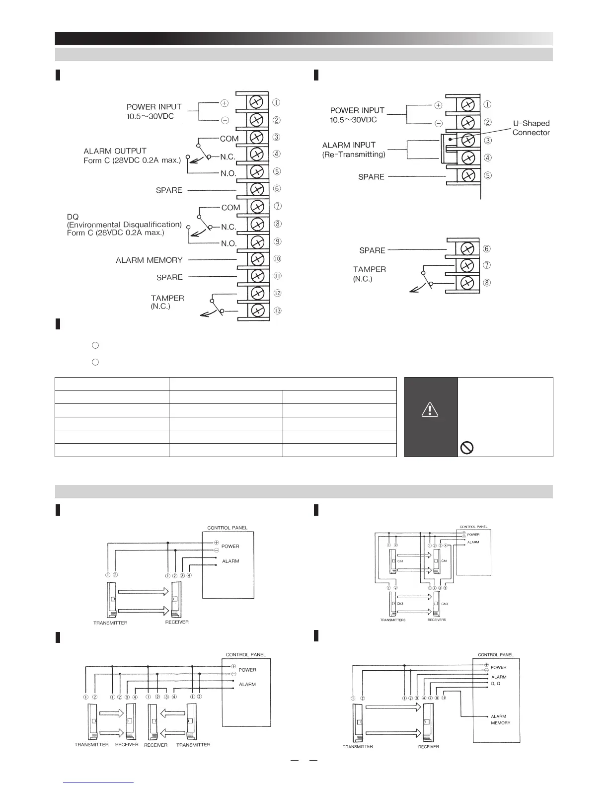
5-1. TERMINAL
Wiring Distance
When using two or more units on one wire, the maximum length is obtained by dividing the wire length listed below by the
number of units used.
Power wires should not exceed the following length.
MODEL AX-350/650TF
WARNING
Do not exceed the voltage
or current rating specifi ed
for any of the terminals
during installation,
doing so might cause fi re
or damage to the devices.
WIRE SIZE 12V DC 24V DC
AWG22 (0.33mm
2
) 980' (300m) 4700' (1400m)
AWG20 (0.52mm
2
) 1500' (470m) 7400' (2250m)
AWG18 (0.83mm
2
) 2450' (750m) 11800' (3600m)
AWG16 (1.31mm
2
) 3900' (1150m) 18700' (5700m)
UL requires AX-350TF/AX-650TF to be connected to a UL listed power supply capable of providing a
norminal input of 12VDC, (10.5~30VDC) 75mA and battery standby time of 4 hours.
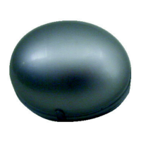
1 Set
2 Set in the line
2 Sets Stacking
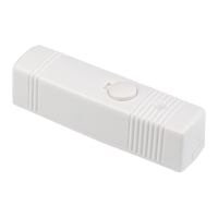
DQ and ALARM MEMORY
5-2. WIRING