8
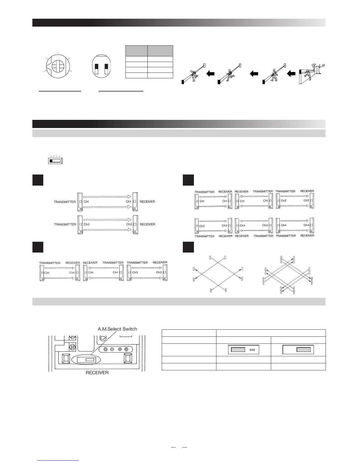
6. BEAM INTERRUPTION TIME ADJUSTMENT
The beam interruption time adjustment is on Receiver unit. This function allows you to match the units sensitivity ti its surroundings. Slower steeings
reduce sensiticity.
CAUTION :
• Speeds shown above are the maximum detectable speeds for each setting. Faster speeds will not be detected. Where birds, newspapers or fl ying
debris can occasionally interrupt the beam, adjust setting to a slower speed (longer interruption period.)
• Beam interruption times exceeding 70 msec do not comply with the requirements in UL639. Intrusion Detection Units.
Interruption
time
Switches
50ms 1:OFF, 2:OFF
100ms 1:OFF, 2:ON
250ms 1:ON, 2:OFF
500ms 1:ON, 2:ON
50msec 100msec 250msec 500msec
Running
(2.4m/s)
Jogging
(1.2m/s)
Walking
(0.5m/s)
Slow movement
(0.3m/s)
[AX-250/500PLUS] [AX-350/650TF]
Selection Dip SwitchAdjustment Volume
7. AX-350/650TF
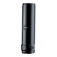
7-1. SELECTABLE BEAM FREQUENCIES
The selectable beam frequencies can be used to avoid unwanted crosstalk that can occur when using multiple photobeams for
long distance or beam stacking applications.
• To select between 4 separate beam frequencies, use the switch provided.
• Make sure the receiver and transmitter that are facing each other are set to the same code.
IMPORTANT Always switch the frequencies TWO channels apart when stacking units on top of one another (See following example).
The upper unit is set on channel 1 while the lower is on channel 3, channel 2 and 4 could have also been used.
1
2 beam stacking
2
Long distance
3
2 beam long distance stacking
4
Perimeter protection
transmitter(Ch1)
receiver(Ch1)
receiver(Ch3)
transmitter(Ch3)
transmitter(Ch1)
receiver(Ch1)
receiver(Ch3)
transmitter(Ch3)
transmitter(Ch1)
transmitter(Ch3)
receiver(Ch1)
receiver(Ch3)
transmitter(Ch2)
transmitter(Ch4)
receiver(Ch2)
receiver(Ch4)
transmitter(Ch3)
transmitter(Ch1)
receiver(Ch3)
receiver(Ch1)
transmitter(Ch4)
transmitter(Ch2)
receiver(Ch4)
receiver(Ch2)
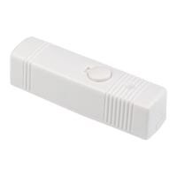
7-2. ALARM MEMORY
1. Wiring
Connect control voltage signal terminal (System arming status voltage output terminal) of control panel to A.M.terminal.
Model AX-350TF, AX-650TF
Type NEGATIVE POSITIVE
A.M.Select Switch
Position
System armed 0~1VDC(grounded) OPEN or + 5~30VDC
System disarmed OPEN or + 5~30VDC 0~1VDC(grounded)
2. Operation of Alarm Memory
If the units is triggered during an armed period, when the system is disarmed, its LED will remain lit to confi rm that it reported the alarm.
• Alarm Memory will not latch while system is disarmed.
• LED operation and alarm output are not affected by alarm memory when system is armed.
3. Reset
Alarm memory resets automatically when system is re-armed.
• Optical, compatible control panel required.
1234
BEAM FREQUENCY
SELECT SWITCH
200
350
100
50
(m/sec)
500
ON
12