DUT
GER
FRE
Note
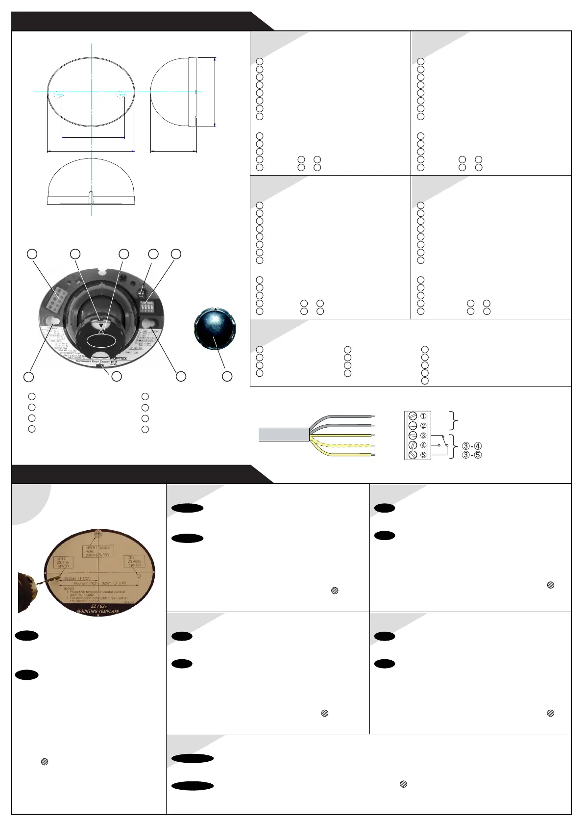
Be sure to install the sensor where it will
not be directly sprayed with rainwater or
snow.
Note
Be sure that the mounting height is within
the value of those in "SPECIFICATION".
1. Affix the Mounting Template to the
mounting surface.
2. Drill two mounting holes (ø 3.4mm or
1/8”).
3. To carry through the wire to the header,
drill (ø 8mm or 5/16”).
4. After drilling the holes, remove the
Mounting Template.
1
SPA
ITA
ITAGER
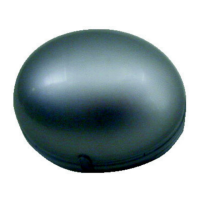
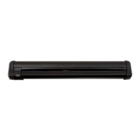
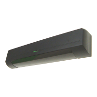
Name of Parts
WIRING: Terminal Block
INSTALLATION
1
Terminal Block
2
Rotating Antenna Unit
3
Standard Lens
4
Sensitivity Potentiometer
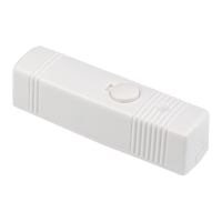
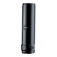
OUTER DIMENSIONS
60 (2 3/8")
82 (3 1/4")
114.5 (4 1/2")
90.5 (3 9/16")
mm (inch)
VERKABELUNG
Hinweis
Sicherstellen, daß der Sensor so angebracht wird, daß er vor
direktem Spritzregen-wasser oder Schnee geschützt ist.
Hinweis
Sicherstellen, dass die Montagehöhe sich innerhalb der Werte
dieser “TECHNISCHEN DATEN” befindet.
1. Montage-Schablone auf der Montagefläche anbringen.
2. Zwei Montagelöcher bohren (ø 3,4 mm oder 1/8”).
3. Zur Kabeldurchführung zur Kopfplatte aufbohren
(ø 8 mm
oder 5/16”).
4. Nach Bohren der Löcher, die Montagesch-ablone abnehmen.
INSTALLAZIONE
Nota
Assicurarsi di installare il sensore in un punto che non venga
colpito direttamente dalla pioggia o dalla neve.
Nota
Assicurarsi che l’altezza di montaggio rientri fra i valori indicati
nella sezione “SPECIFICHE”.
1. Applicare il modello di montaggio sulla superficie di montaggio.
2. Praticare due fori di montaggio (ø 3,4 mm).
3. Per portare il cablaggio alla testate, praticare un foro
(ø 8
mm).
4. Dopo aver praticato i fori, togliere il modello di montaggio.
INSTALACIÓN
Nota
Asegúrese de instalar el sensor donde la lluvia o la nieve no lo
mojen directamente.
Nota
Compruebe que la altura de montaje se encuentre dentro de los
valores establecidos en “ESPECIFICACIONES”.
1. Fijar la plantilla de montaje sobre la superficie de montaje.
2. Perforar dos orificios de montaje (ø 3,4 mm o 1/8”).
3. Para atravesar el cable hasta el travesaño, perforar
(ø 8
mm o 5/16”).
4. Una vez realizados los orificios, retirar la plantilla de montaje.
5
Dipswitches
6
Mounting Holes
7
Operation Indicator
8
Spot Lens
1 3 4 5
6
7 6 8
Dimensioni esterne
Teilebezeichnungen
1
Anschlußklemmleiste
2
Drehantennenvorrichtung
3
Standardlinse
4
Empfindlichkeit-Potentiometer
5
DIP-Schalter
6
Montagelöcher
7
Betriebsanzeige
8
Linsenscheinwerfer
VERKABELUNG: Anschlußklemmleiste
1
Grau Stromversorgung
}
2
Grau 12 bis 24V WS / 12 bis 30V GS
3
Gelb Relais
4
(Gelb)
3
–
4
(S.O.)
5
Gelb
3
–
5
(S.G.)
Nomi delle parti
1
Blocco Terminale
2
Antenna Rotante
3
Lente Standard
4
Potenziometro di Sensibilità
5
Interruttori
6
Fori di Montaggio
7
Indicatore di Funzionamento
8
Lente Spot
Collegamento: Blocco di morsetti
1
Grigio Alimentazione
}
2
Grigio da 12 a 24V C.A./ da 12 a 30V C.C.
3
Giallo Relè
4
(Giallo)
3
–
4
(N.A.)
5
Giallo
3
–
5
(N.C.)
2
Außendimension
FRE
Dénomination des pièces
1
Bornier
2
Antenne rotative
3
Lentille standard
4
Potentiomètre de sensibilité
5
Microrupteurs
6
Trous de montage
7
Témoin de fonctionnement
8
Lentille spot
CABLAGE: Bornier
1
Gris Alimentation
}
2
Gris 12 à 24 V CA / 12 à 30 V CC
3
Jaune Relais
4
(Jaune)
3
–
4
(Normalement ouvert)
5
Jaune
3
–
5
(Normalement fermé)
Dimensions exterieures
SPA
Dimensiones exteriores
NOMBRE DE LAS PIEZAS
1
Bloque de conexiones
2
Antena orientable
3
Lente estándar
4
Potenciómetro de sensibilidad
5
Interruptores
6
Orificios de montaje
7
Indicador func.
8
Lente centradora
Cableado: bloque de conexiones
1
Gris Voltaje de la corriente de
}
2
Gris 12 a 24 V CA / de 12 a 30 V CC
3
Amarillo Relé
4
(Amarillo)
3
–
4
(NO)
5
Amarillo
3
–
5
(NC)
DUT
Namen van onderdelen
1
Aansluitingen
2
Roterende antenne
3
Standaard lens
4
Potentiometer
gevoeligheidsinstelling
Buitenafmetingen
5
Dipschakelaars
6
Bevestigingsgaten
7
Controlelampje
8
Spotlens
BEDRADING: Aansluitingen
1
Grijs Stroomvoorziening
}
2
Grijs 12 t/m 24 V AC / 12 t/m 30 V DC
3
Geel Relais
4
Geel (N.O.)
5
Geel (N.C.)
INSTALLATION
Nota
Assurez-vous d’installer le détecteur dans un endroit où il n’est
pas soumis directement à la pluie ou à la neige.
Nota
Respecter la hauteur de montage indiquée dans
“SPECIFICATIONS”.
1. Appliquez le gabarit sur la surface de montage.
2. Percez deux trous (ø 3,4 mm).
3. Pour passer le câble vers la boutisse, percez
(ø 8 mm).
4. Après perçage des trous, enlevez le gabarit.
INSTALLATIE
Opmerking
U moet de sensor installeren op een plek waar deze niet direct
geraakt kan worden door regenwater, sneeuw en dergelijke.
Opmerking
De bevestigingshoogte moet vallen binnen de onder de
“TECHNISCHE GEGEVENS” vermelde waarden.
1. Bevestig het bevestigingssjabloon op de gewenste plek.
2. Boor twee bevestigingsgaatjes (ø 3,4 mm of 1/8”).
3. Boor
om de bedrading naar het toestel te kunnen leiden (ø
8 mm of 5/16”).
4. Verwijder het bevestigingssjabloon nadat u de vereiste gaten
geboord heeft.
Grey
Yellow
Grey
(Yellow)
Yellow
Power Supply
12 to 24V AC / 12 to 30V DC
Relay
N.O.
N.C.
}}
}
}
}
 Loading...