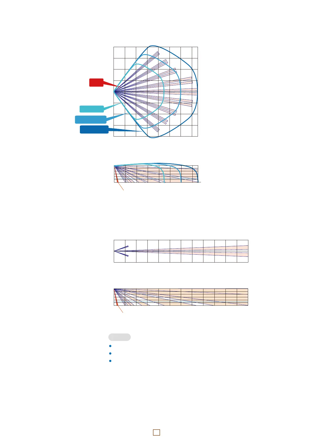
Wide
- Top view -
Wide
- Side view -
Narrow
- Top view -
Narrow
- Side view -
- Detection area
The * 2.4 dotted line indicates the recommended mounting height.
When “Narrow” is selected in the lens setting, MW detection will be stopped.
Down zone * can be deleted by switch setting (See 2-4).
NOTE
0 2 4 6 8 10 12 14 16 18 20 22 24 m
2
0
2 m
0 10 20 30 40 50 60 70 80 ft.
6
3
0
3
6 ft.
0
3
6
9 ft.
0
1
2
* 2.4
3 m
0 2 4 6 8 10 12 14 16 18 20 22 24 m
0 10 20 30 40 50 60 70 80 ft.
Downzone*
16
8
6
4
2
0
2
4
6
8 m
0 10 20 30 40 50 ft.
20
10
0
10
20 ft.
0 2 4 6 8 10 12 14 m
MW
High
MW
Middle
PIR
MW Low
0
1
2
* 2.4
3 m
0
3
6
9 ft.
0 2 4 6 8 10 12 14 m
0 10 20 30 40 50 ft.
Downzone*
 Loading...