Step 10
Step 8
Step 9
Step 6
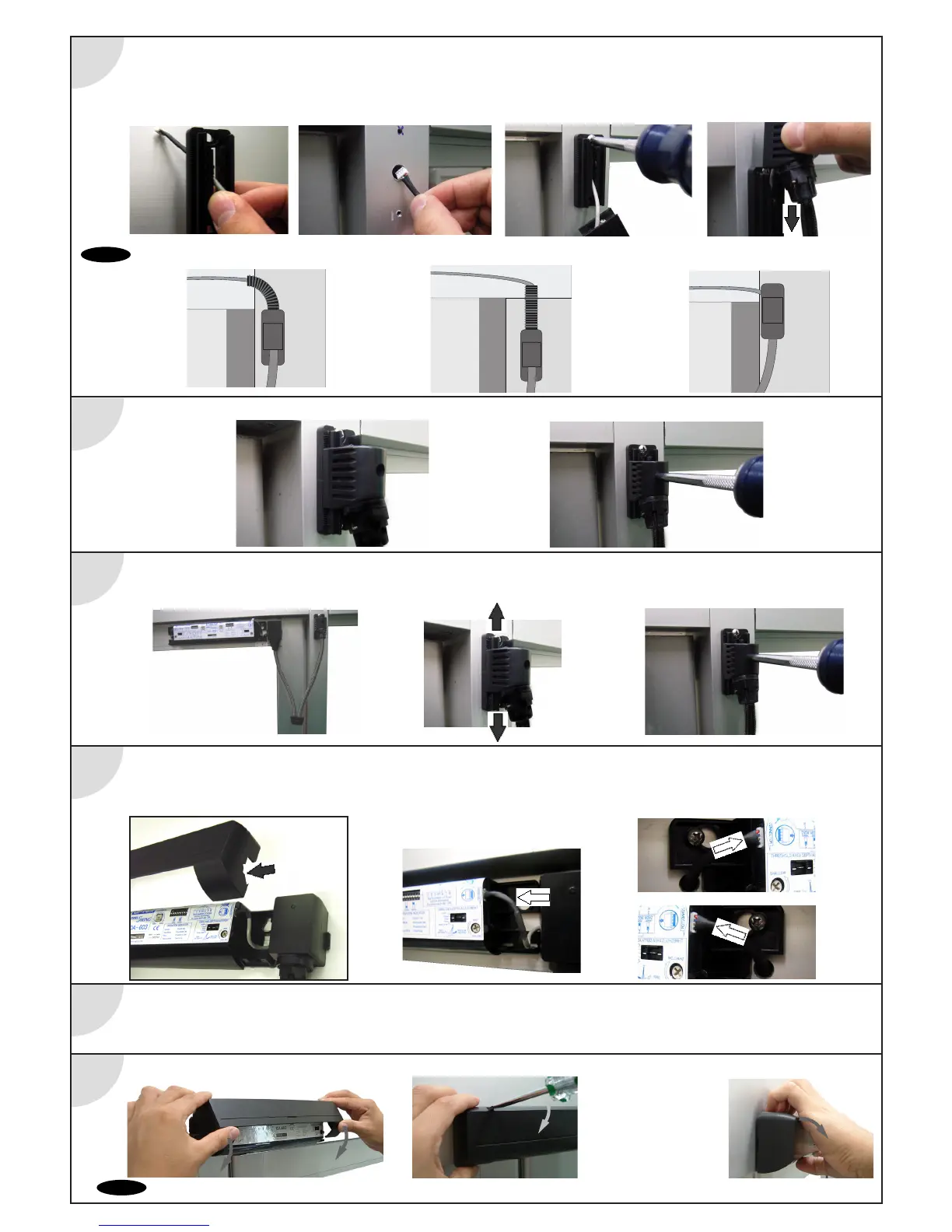
1. For concealed wiring feed the connector thru the wiring base and then the 3/8" cable hole and into the header. For surface wiring
(see note below) do not route wire thru the wiring base.
2.Properly position and securely fasten the wiring base to the jamb (small screw located on side of wiring base indicates bottom of base).
3.Feed the remainder of the cable thru the base and into the header then slide the wiring cover onto the wiring base from the top down.
Step 7
1.Temporarily position the wiring cover on the center of the base vertically.
1.Open and close the door leaf to determine the best location for the wiring cover on the base plate.
On applications where the loop is mounted on the swing side, make sure the loop does not touch the door panel throughout the door travel.
2.Once the ideal position is determined, turn the screw in the back of the cover clockwise to secure the cover in place.
1. Remove knockouts for OA 603 sensor cover on loop side only!
2. Connect the cable from position sensor to the OA-603.
3. Connect pass thru cable to both OA-603 sensor heads.
How to remove the cover
Hold the top and remove the cover.
Place the cover on the top then fit it on.
Insert the flathead screw driver
and push it down
as shown in the picture.
If desired, sensor covers can be left off until initial setup and final adjustments are performed.
Step 11
Threshold Area
Sensitivity
Potentiometer
1-4
Complete wiring of OC-904 and perform intitial setup. Refer to OC-904 instruction manual and Wiring Matrix for wiring details.
Refer to Elite manual (page 1-6) for initial setup details. Once complete return to step 11.
KNOCK OUT