16
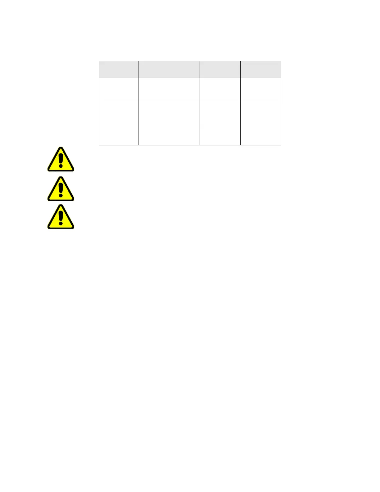
Recommended Hose Selection Table
CAUTION: Under-sizing the process hose will result in greater than typical pressure drop
and may cause inadequate process pressure to be delivered. This may harm your process
equipment and/or cause unnecessary wear on the chiller motor and pump.
CAUTION: The fittings are connected to a manifold plate attached to the unit. Do not over
tighten fittings or failure may occur.
CAUTION: Never connect the fittings to your building water supply or any pressurized water
source.
6.3 Chilled Water Lines
All chilled water piping should be adequately insulated to prevent condensation. If water is
allowed to condense on the piping, the state change of the water from gas to liquid will result
in a substantial heat load which becomes an additional burden for the chiller.
Standard portable chillers have been designed for a nominal flow of 2.4 GPM per ton at
nominal conditions. During normal full-load operation with 55°F (10°C) coolant supplied to the
process, this nominal flow rate will result in a 65°F (15°C) coolant returned from the
process. The nominal flow rate for each chiller is shown above in the Recommended Hose
Selection Table. This table also provides the maximum flow rate for each chiller. The
maximum flow rate should not be exceeded unless the chiller was specifically ordered to
handle high flow conditions. If the process cannot handle the full nominal flow from the
chiller, the excess water flow will simply bypass the process through the bypass line inside
the chiller.
The importance of properly sized piping between the chiller and process cannot be
overemphasized. In general, run full size piping out to the process and then reduce the pipe
size to match the connections on the process equipment. One of the most common causes of
unsatisfactory chiller performance is poorly designed piping. Avoid unnecessarily long lengths
of hoses or quick disconnect fittings which offer high resistance to water flow.
When manifolds are required for water distribution, they should be installed as close to the
use point as possible. Provide flow balancing valves at each machine to assure adequate
water distribution in the entire system.
Standard
Model OTC
Standard Flow Rating
Minimum
Hose Size
Hose Length
from Machine
.25A, .33A,
.5A, .75A,
1.0A, 1.5A
2.3 GPM @ 65 PSI
4 GPM @ 65 PSI
≥ ¾” ID
≥ 1” ID
< 10’
>10’
2.0A, 3.0A,
5.0A
5 to 7 GPM @ 55 PSI
12 GPM @ 53 PSI
≥ 1-1/4” ID
≥ 1-1/2” ID
< 10’
> 10’
7.5A, 10A
18 to 30 GPM @ 56 PSI
≥ 1-1/2” ID
≥ 2” ID
< 10’
> 10’