23
7.8 Fluid Bypass Valve Setting and Adjustment
The chiller is equipped with a mechanical pressure-activated internal bypass valve. The
bypass valve comes factory set. If you do not want to operate at the factory set pressure, or
do not know what your operation pressure should be, start at a lower operation pressure.
Reduce the pressure by loosening the lock ring and turning the bypass valve
counterclockwise (unscrew outward) before starting the chiller. It may be necessary to
remove an access cap on the bypass valve.
With the chiller fully connected and running, read a pressure gage attached to your process
fluid line and turn the bypass adjustment knob clockwise to reach your desired pressure.
Tighten the lock ring when finished.
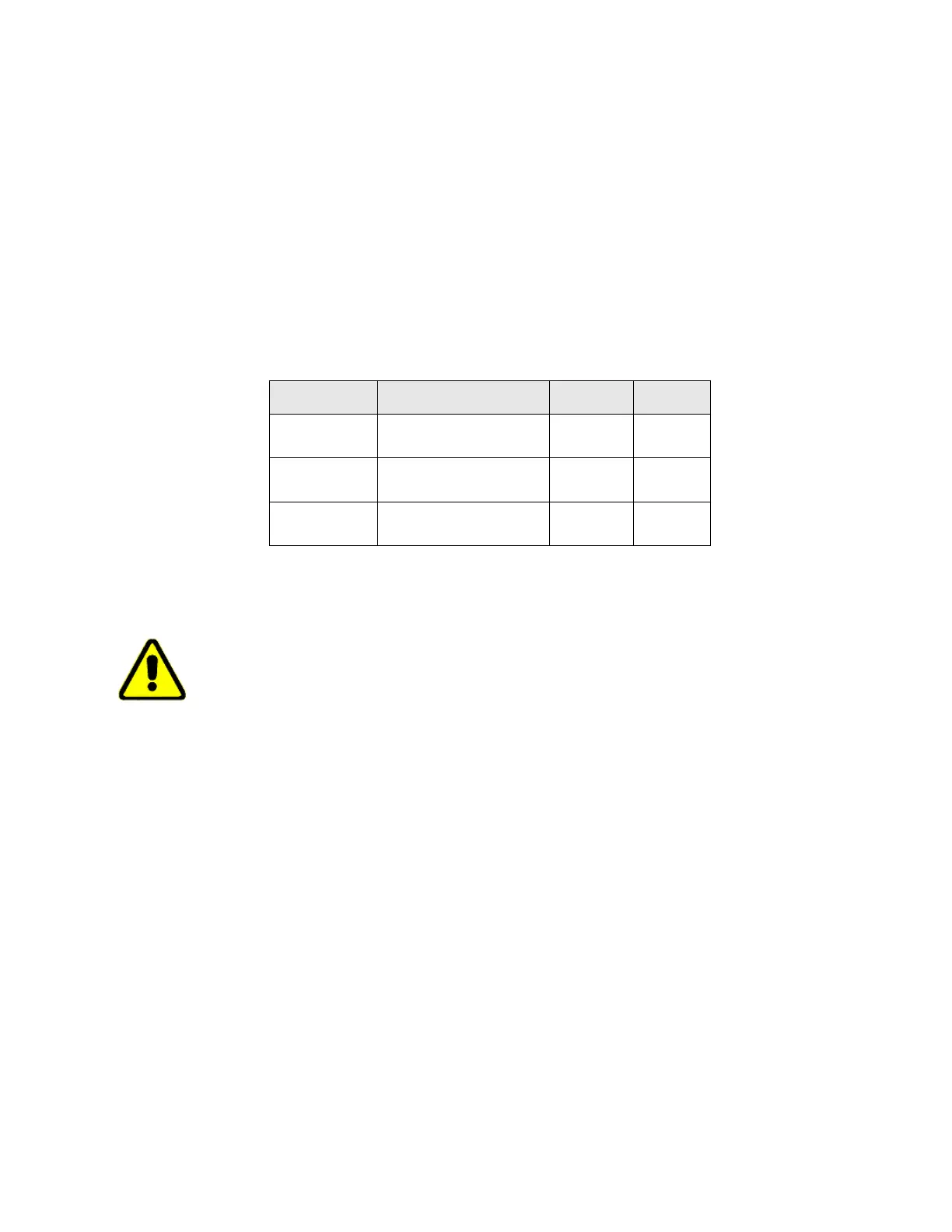
Bypass Set-Point Table
Model OTC
Standard Pump Pump ID
Set-point
.25A, .33A, .5A,
.75A, 1.0A, 1.5A
1/3 HP motor and positive
displacement pump
P1, P3
65 PSI
2.0A
1 HP motor and centrifugal
pump
C2
45 PSI
3.0A
1.5 HP motor and
centrifugal pump
C3 55 PSI
NOTE: Refer to Page 31 for Pump Identification code.
NOTE: Couplings and clamps are preferred to quick connect fittings because they have the
potential for restricting the flow rate.
CAUTION: Please contact OPTI TEMP if your process is equipped with a valve, which may
periodically interrupt flow to the process. Bypass settings may be critical to protect the
system from damage!
It is recommended that the valve in the supply line to the process be throttled (closed slowly)
until the bypass valve just starts to feed. By putting your hand on the valve and bypass line
you will be able to feel when the valve starts to open. This allows the air to be cleared from
the bypass line.
7.9 System Fluid Drainage
1. Remove power from the unit.
2. Using the system drain connection (if applicable) open the petcock drain, located on the
unit and drain as much fluid as possible.
3. After the fluid system drain has been opened and fluid has left the unit, disconnect the
process connections from the chiller.
4. Drain any additional fluid out of the process connections.
5. Unscrew the filtration housings (if applicable) from their top and empty the fluid trapped
inside the filter housing. Screw back on the emptied filter housings.
6. Close the system drain, screw a cap on the process fluid connections and the system is
now ready for transport in warm climates.
Additional procedures for cold climate conditions:
1. Apply power back to the unit.
2. Add enough propylene glycol into the fluid reservoir to ensure the fluid tank level float is
met. Typically this requires > 25% of the fluid reservoir to be filled.
3. Connect a short-circuit loop hose to the process supply and process return connections.