THE CLIMATE FACTORY/USER MANUALS/OPTICLIMATE SPLIT (INVERTER)
www.theclimatefactory.com info@theclimatefactory.com
© The Climate Factory
ELECTRICAL CONNECTION
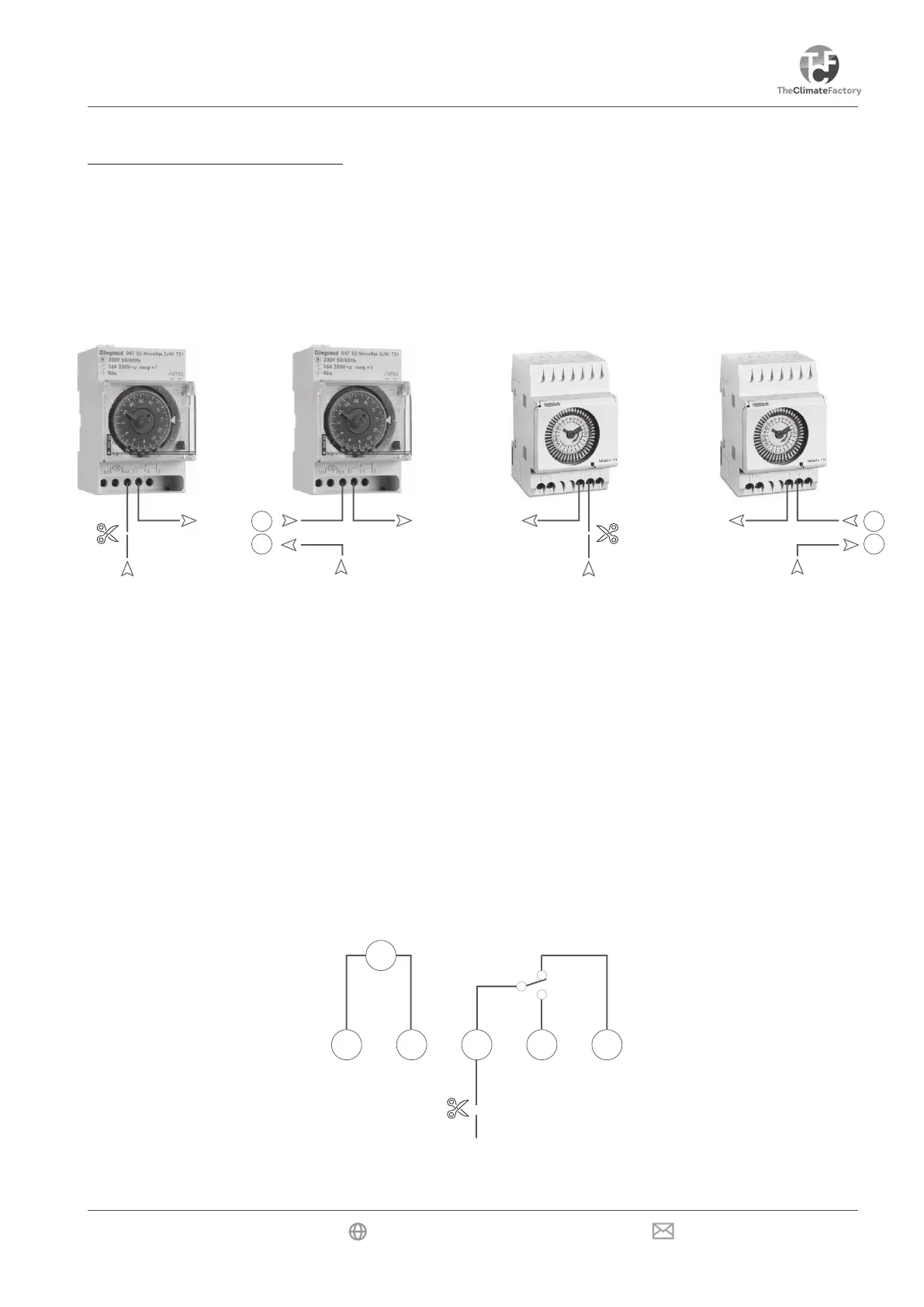
Using this safeguard, the OptiClimate can switch off the heat sources (e.g. lamps) when the temperature in
a room becomes too high. The unit has a terminal that can be connected to the timer of a control panel, for
example. The feed wire running to the switch in the timer should be interrupted for this purpose. Terminal 1, for
example, is for a Grasslin clock and terminal 4 for a LeGrand timer.
LeGrand nilssarG
16
15
16
15
The two ends should be connected to terminals 15 & 16 on the terminal strip in the electrical compartment of
the OptiClimate. The OptiClimate supplies the power for the timer.
The OptiClimate supplies the power for the timer. If the room temperature exceeds 35°C, the OptiClimate will
interrupt the circuit, switching off the heat sources. ERROR 15 is then displayed on the remote control.
Always refer to the timer manufacturer’s manual if a model other than the one shown
is used.
M
L N