APPLICATIONS AND CONNECTIONS
14
I
NSTALLATION MANUAL FOR OPTIMUS 4G LTE RANGE OF INTERCOM UNITS
INSTALLING OR REPLACING THE SIM CARD
Ensure that the Unit is switched off at the plug before inserting or removing the micro SIM card.
When the micro SIM card is inserted CORRECTLY:
1. The Green “OK” LED is dual purpose
a. It will illuminate indicating that power is being received by the PCB
b. It will indicate the signal strength (RSSI) through a number of slow ashes:
i. 1 Flash = 1 Bar.
ii. Max 4 Flashes = 4 Bars.
2. The Blue “Network Status” LED will indicate connection status:
a. Off = Disconnected.
b. On solid = Connecting to the Network,
followed by:
c. Slow Flashing = Connected.
Should the micro SIM be inserted INCORRECTLY or not detected?
1. The Green “OK” LED will slow ash for approximately 20 seconds, then fast ash.
2. The Blue “Network Status” LED will be permanently On.
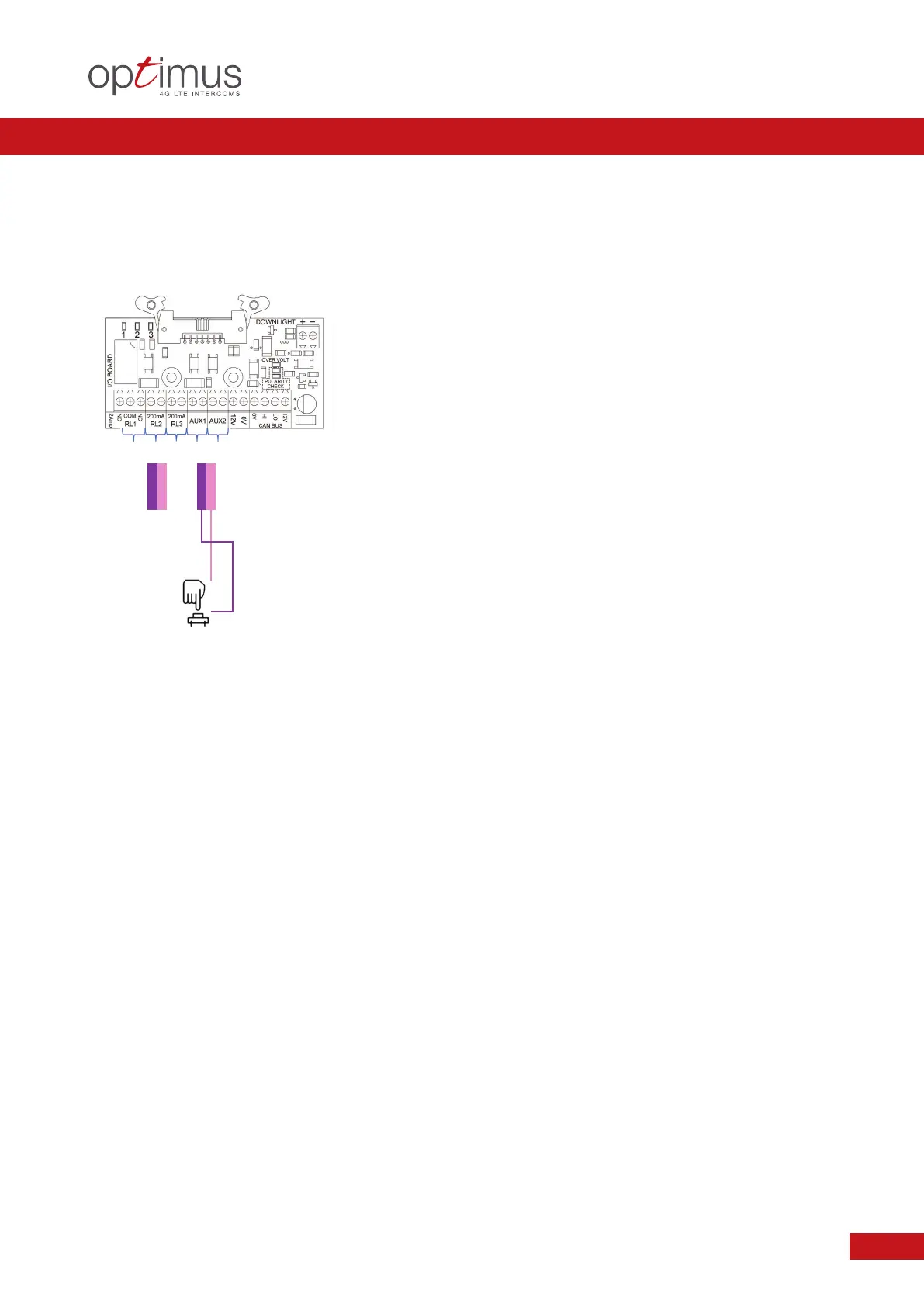
EXAMPLE 6.0
Application: ALTERNATIVE EXIT CONTROL USING AUXILIARY INPUT
Condition: AUXILIARY INPUT TO ACTIVATE SET RELAY. EXAMPLE: PUSH TO EXIT
RELAY ACTION RESULT
A
UX 1 or 2 Pulse Close >70ms NO Activates Relay of choice
(RL1, RL2, RL3) as set up
in the Programming
z
Methods of Relay Operation can include: DTMF Tone / Facia PINS / Authorisation Recognition.
z
Typical examples not common to all systems. Please follow the DHF Code of Practice Guide accordingly.
Exit Button
or similar
A
ctivates
Relay of
choice
(RL1,RL2, RL3)
E
ither Aux 1 or Aux 2 as determined by Programming