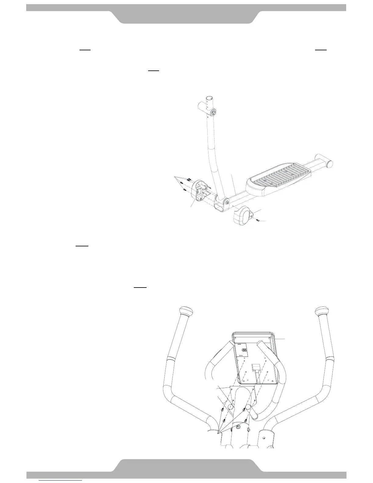
13. Foot Tube Pivot Decorative Cover Installation
13.1 Assemble One set of Foot Tube Pivot Decorative Cover –A/B [C03/C18] onto Left Foot Tube [A05] with Five
Screws [B19] and tighten firmly.
13.2 Refer the same step to assemble the One set of Foot Tube Pivot Decorative Cover –A/B [C03/C18] onto Right
Foot Tube [A06].
[Remove/Tighten screws with the Hex Tool with Phillips Screwdriver provided.]
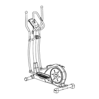
14. Computer Installation
14.1 Remove Four Screws [B21] from the bottom of Computer [D02].
14.2 Connect all matching connectors of cables which from Stationary Handlebar [A09] and Computer [D02].
14.3 Slide the extra length cables into the opening hole of Stationary Handlebar [A09].
14.4 There is the computer plate on the top of the Stationary Handlebar [A09]. Position the Computer [D02] on the
computer plate and secure with Four Screws [B21] which were removed from step 14.1.
[Remove/Tighten screws with the Hex Tool with Phillips Screwdriver provided.]
Attention: Cables can't be folded.