122
UTILISATION
7
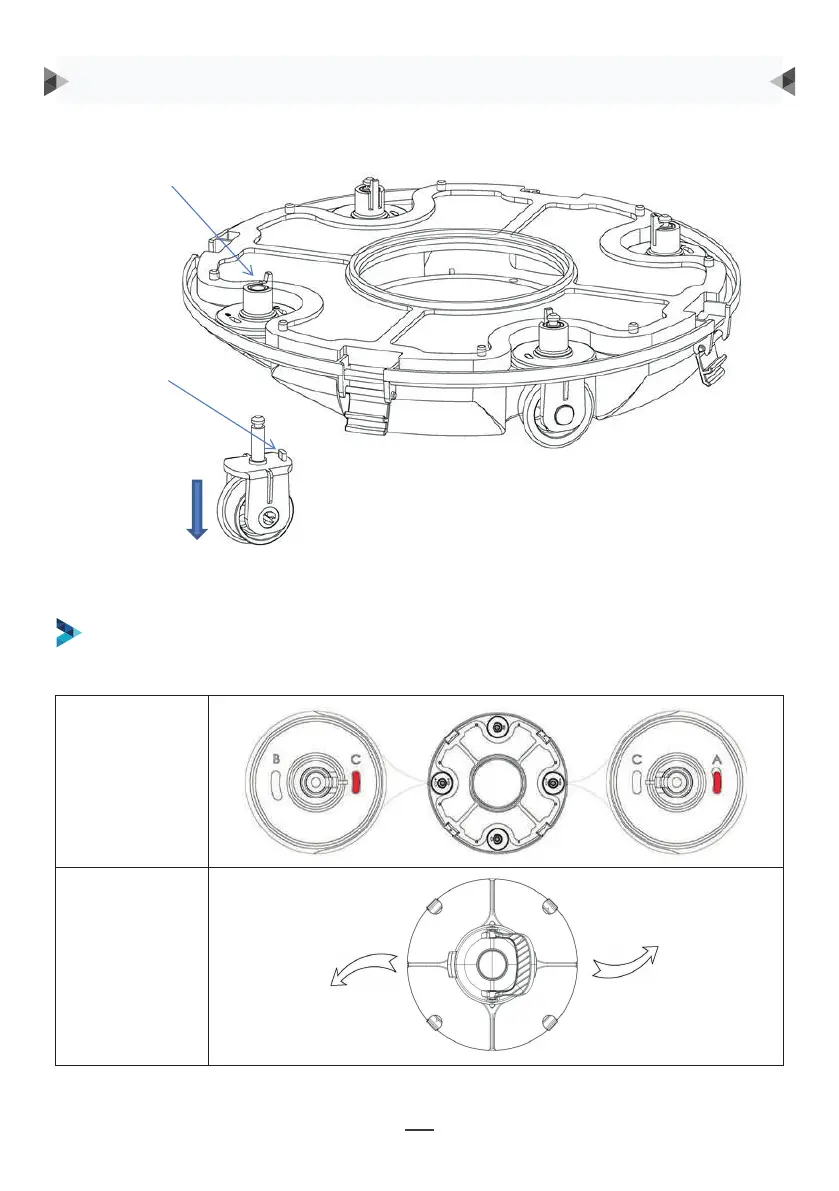
Groove for wheel limit piles
A, B, C are printed on the groove of the wheel limit pile of the chassis. Wheel limit piles will be
installed by default on C (left) and A (right).
Wheel buckle
Wheel limit pile
As shown in the figure, push the wheel buckle, pull down the wheel components, and remove them.
Unghiul roților
Calea de rulare
SUNT RECOMANDATE PATRU SETĂRI PENTRU ROȚI:
Setarea 1: setare implicită: C-A, pentru majoritatea bazinelor de înot
Element de fixare a roții
Element de
limitare a roții
După cum este indicat în figură, împingeți elementul
de fixare a roții, trageți în jos componentele roții și
scoateți-o.
Apoi reinstalați elementul de limitare în cadrul de deplasare pentru a realiza diferitele căi
de rulare.
INSTRUCȚIUNI DE OPERARE
8
Then re-install the limit pile into chassis to realize the different running paths.
b. Four settings for wheels are recommended:
Setting 1: default setting: B-C, for most of pools
9
Setting 2: C-A, when the turning angle is too large
9
Setting 2: C-A, when the turning angle is too large
9
Setting 2: C-A, when the turning angle is too large