154
UTILISATION
7
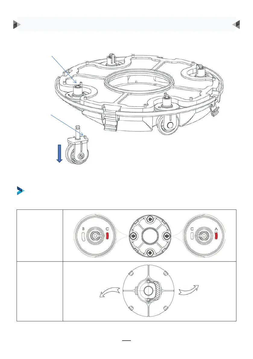
Groove for wheel limit piles
A, B, C are printed on the groove of the wheel limit pile of the chassis. Wheel limit piles will be
installed by default on C (left) and A (right).
Wheel buckle
Wheel limit pile
As shown in the figure, push the wheel buckle, pull down the wheel components, and remove them.
Úhel kolečka
Dráha
DOPORUČUJÍ SE ČTYŘI POLOHY NASTAVENÍ KOLEČEK:
1. nastavení: výchozí nastavení: C-A, pro většinu bazénů
Úchyt kolečka
Zarážka kolečka
Zatlačte na úchyt kolečka, jak je znázorněno na
obrázku, stáhněte komponenty kolečka a vyjměte je.
Poté znovu do podvozku nainstalujte zarážku za účelem vymezení různých drah.
POKYNY PRO POUŽITÍ
8
Then re-install the limit pile into chassis to realize the different running paths.
b. Four settings for wheels are recommended:
Setting 1: default setting: B-C, for most of pools
9
Setting 2: C-A, when the turning angle is too large
9
Setting 2: C-A, when the turning angle is too large
9
Setting 2: C-A, when the turning angle is too large