10
UTILISATION
7
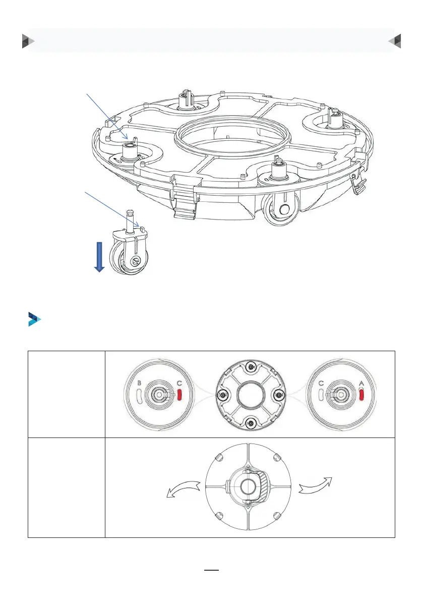
Groove for wheel limit piles
A, B, C are printed on the groove of the wheel limit pile of the chassis. Wheel limit piles will be
installed by default on C (left) and A (right).
Wheel buckle
Wheel limit pile
As shown in the figure, push the wheel buckle, pull down the wheel components, and remove them.
Radwinkel
Laufweg
ES WERDEN VIER EINSTELLUNGEN FÜR DIE RÄDER EMPFOHLEN:
Einstellung 1: Standardeinstellung: C-A, für die meisten Schwimmbecken geeignet
Radschnalle
Radbegrenzungspfahl
Drücken Sie, wie in der Abbildung gezeigt, auf die
Radschnalle, ziehen Sie die Radkomponenten nach
unten und entfernen Sie diese.
Bauen Sie anschließend den Begrenzungspfahl wieder in das Fahrgestell ein, um die
unterschiedlichen Laufwege zu realisieren.
BEDIENUNGSANLEITUNG
8
Then re-install the limit pile into chassis to realize the different running paths.
b. Four settings for wheels are recommended:
Setting 1: default setting: B-C, for most of pools
9
Setting 2: C-A, when the turning angle is too large
9
Setting 2: C-A, when the turning angle is too large
9
Setting 2: C-A, when the turning angle is too large