58
UTILISATION
7
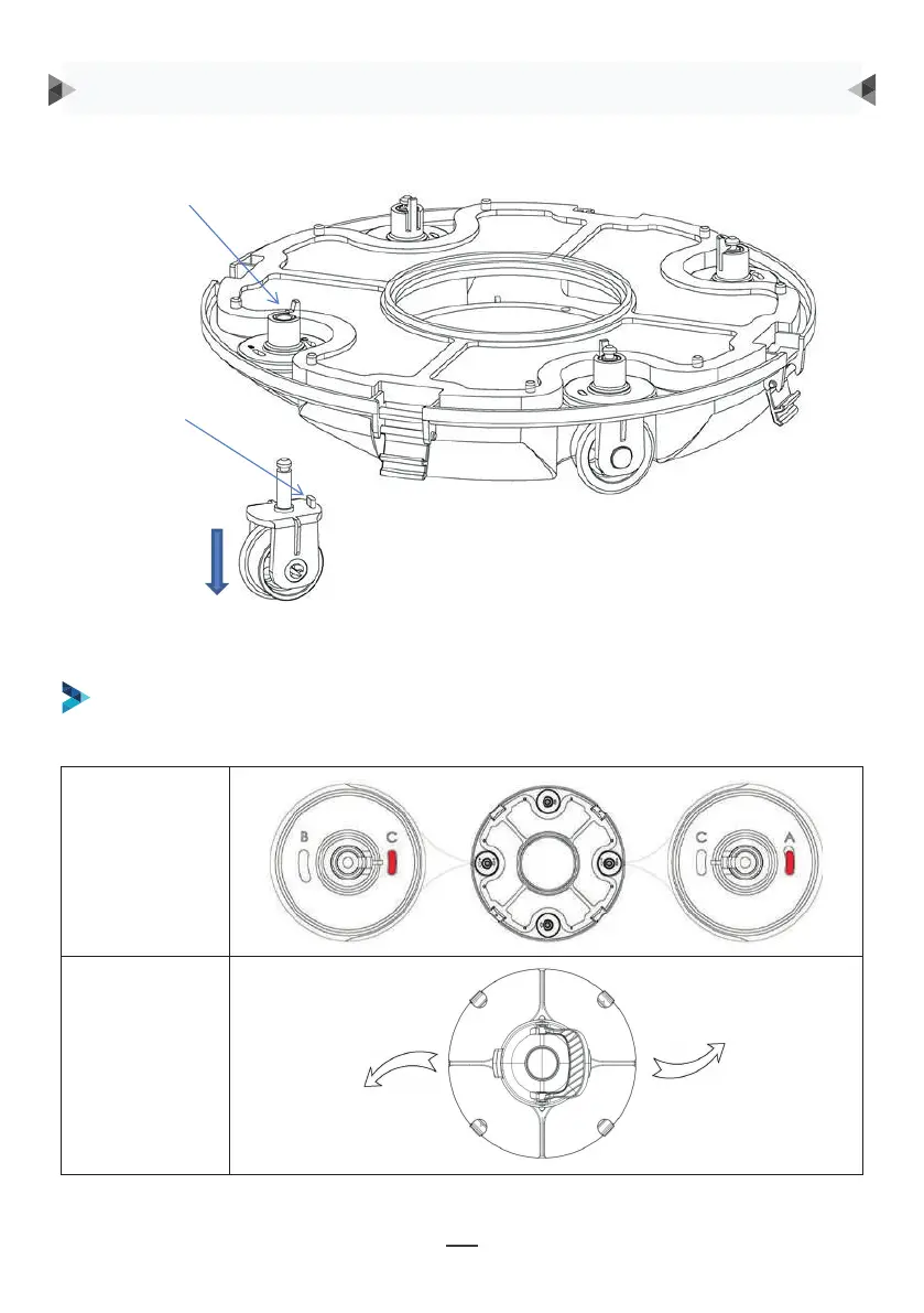
Groove for wheel limit piles
A, B, C are printed on the groove of the wheel limit pile of the chassis. Wheel limit piles will be
installed by default on C (left) and A (right).
Wheel buckle
Wheel limit pile
As shown in the figure, push the wheel buckle, pull down the wheel components, and remove them.
Angolo delle
ruote
Percorso
DI SEGUITO, SONO ELENCATE QUATTRO CONFIGURAZIONI CONSIGLIATE:
Configurazione 1: Default: C-A, per la maggior parte delle piscine
Clip ruote
Fermi ruote
Come si vede in figura, bisogna spingere la clip, tirare
giù i componenti della ruota e rimuoverli.
Dopodiché bisogna reinstallarli nel telaio anché possano entrare in vigore i nuovi
percorsi di funzionamento.
ISTRUZIONI D’USO
8
Then re-install the limit pile into chassis to realize the different running paths.
b. Four settings for wheels are recommended:
Setting 1: default setting: B-C, for most of pools
9
Setting 2: C-A, when the turning angle is too large
9
Setting 2: C-A, when the turning angle is too large
9
Setting 2: C-A, when the turning angle is too large