9
UTILISATION
6
f. Power off the cleaner after use.
h. Do not touch the wall to avoid scratching the wall or damaging the cleaner when putting into or
lifting out of the pool.
g. Hold the cleaner on the water surface for 10-15 seconds until it empties before removing from
the pool.
h. Grab the floating handle and pull at the rope for lifting it on the water surface, and then grasp
its handle to remove it from the pool.
4.2 Quick operation
a. Plug in the cleaner using the supplied adapter and charging line to charge the battery.
* Power off the cleaner before charging.
* Clean the charging port before charging.
* Red charging indicator indicates the battery is charging.
* Green charging indicator indicates charging is finished.
b. Put the cleaner into water and let it stand horizontally for 5-6 seconds to discharge the air inside
it. Press the switch to power on the cleaner.
c. It will automatically reverse when it touches the wall.
d. The cleaner will stop running after completing the working cycle. The floating handle can be
hooked by a hook with a lengthened connecting rod, and the cleaner is pulled to the edge of the
pool.
e. Power-off operation: the buzzer will be alarming when lifting out of the pool. Press the switch
to OFF and the cleaner will be shut down. Always clean the filter tray after use.
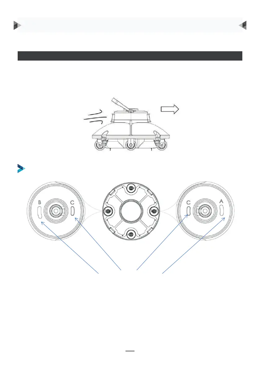
4.3 Functions and adjustment of wheels
There are 4 wheels on the cleaner, of which the left and right wheels are fixed. The front and back
wheels can be selectively adjusted according to different conditions so as to adjust the running path
of the cleaner.
a. Setting wheel angle and running path
EINSTELLUNG VON RADWINKEL UND LAUFWEG
FUNKTIONEN UND EINSTELLUNG DER RÄDER
Der Reiniger verfügt über vier Räder, von denen das linke und das rechte Rad feststehen.
Die vorderen und hinteren Räder können je nach den unterschiedlichen Bedingungen
selektiv eingestellt werden, um den Laufweg des Reinigers anzupassen.
A, B, C sind auf der Rille des Radbegrenzungspfahls des Fahrgestells aufgedruckt.
Standardmäßig werden auf C (links) und A (rechts) Radbegrenzungspfähle installiert.
Rillen für Radbegrenzungspfähle
BEDIENUNGSANLEITUNG
7
Groove for wheel limit piles
A, B, C are printed on the groove of the wheel limit pile of the chassis. Wheel limit piles will be
installed by default on C (left) and A (right).
Wheel buckle
Wheel limit pile
As shown in the figure, push the wheel buckle, pull down the wheel components, and remove them.
 Loading...