74
UTILISATION
7
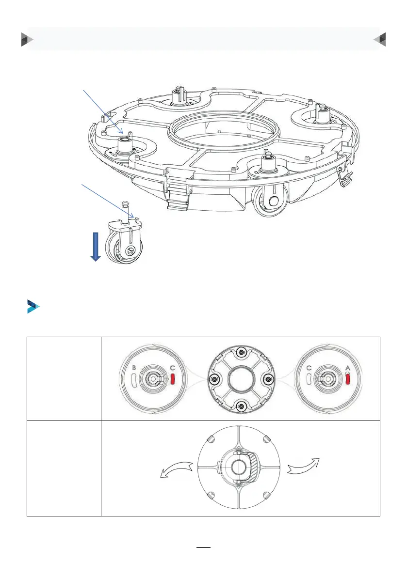
Groove for wheel limit piles
A, B, C are printed on the groove of the wheel limit pile of the chassis. Wheel limit piles will be
installed by default on C (left) and A (right).
Wheel buckle
Wheel limit pile
As shown in the figure, push the wheel buckle, pull down the wheel components, and remove them.
Ángulo de la
rueda
Trayectoria
SE RECOMIENDAN CUATRO CONFIGURACIONES PARA LAS RUEDAS:
Configuración 1: configuración por defecto: C-A, para la mayoría de las piscinas
Hebilla de rueda
Tope de rueda
Como se muestra en la figura, presione la hebilla de la
rueda, tire hacia abajo de los componentes de la rueda
y retírelos.
A continuación, vuelva a montar el tope en el chasis para establecer las diversas
trayectorias de funcionamiento.
INSTRUCCIONES DE FUNCIONAMIENTO
8
Then re-install the limit pile into chassis to realize the different running paths.
b. Four settings for wheels are recommended:
Setting 1: default setting: B-C, for most of pools
9
Setting 2: C-A, when the turning angle is too large
9
Setting 2: C-A, when the turning angle is too large
9
Setting 2: C-A, when the turning angle is too large