90
UTILISATION
7
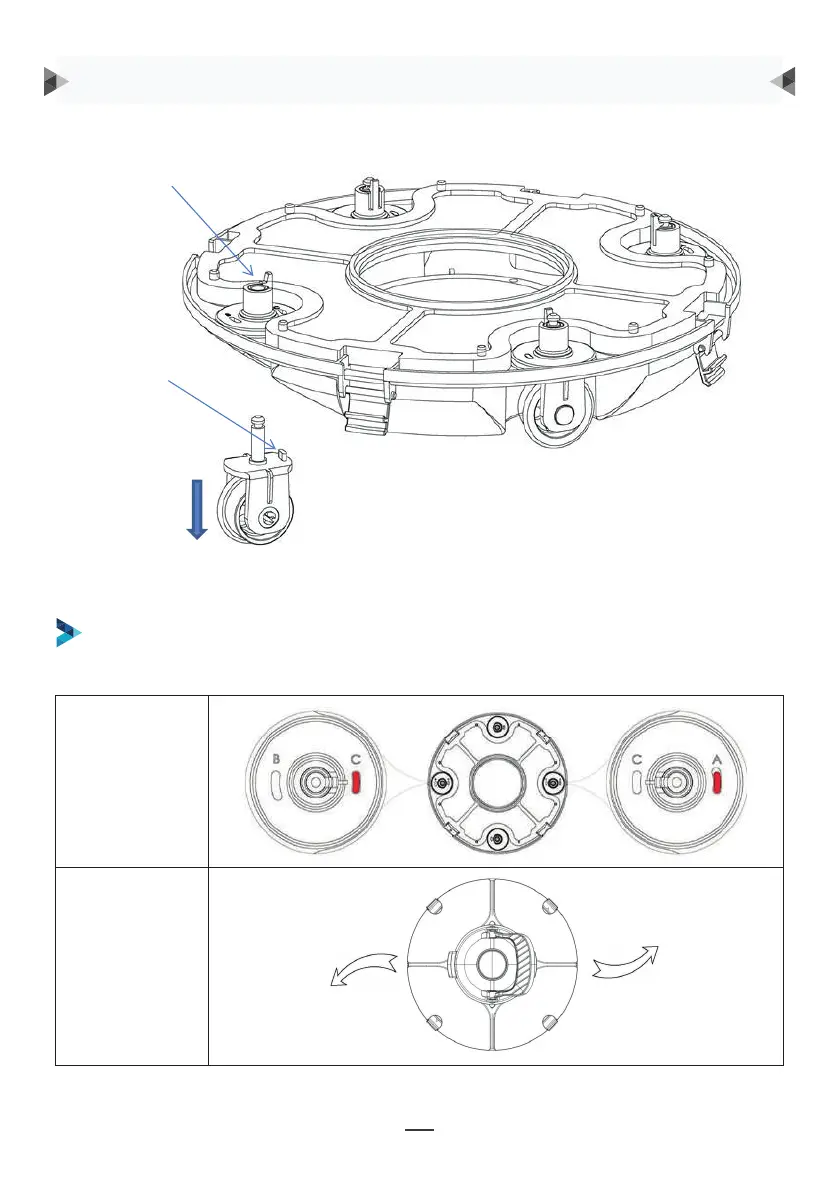
Groove for wheel limit piles
A, B, C are printed on the groove of the wheel limit pile of the chassis. Wheel limit piles will be
installed by default on C (left) and A (right).
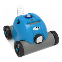
Wheel buckle
Wheel limit pile
As shown in the figure, push the wheel buckle, pull down the wheel components, and remove them.
Ângulo da roda
Trajetória de
funcionamento
SÃO RECOMENDADOS QUATRO AJUSTES PARA AS RODAS:
Regulação 1: predefinição: C-A, para a maioria das piscinas
Fivela da roda
Pilha de limite
das rodas
Como se apresenta na figura, empurre a fivela da roda,
puxe para baixo os componentes da roda, e remova-os.
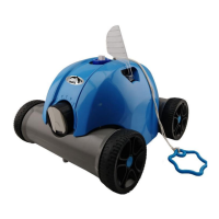
Em seguida, reinstale a pilha de limite no chassis para realizar as diferentes trajetórias
de funcionamento.
INSTRUÇÕES DE FUNCIONAMENTO
8
Then re-install the limit pile into chassis to realize the different running paths.
b. Four settings for wheels are recommended:
Setting 1: default setting: B-C, for most of pools
9
Setting 2: C-A, when the turning angle is too large
9
Setting 2: C-A, when the turning angle is too large
9
Setting 2: C-A, when the turning angle is too large