This document serves as an instruction manual for the OREC Grassland Mower Rabbit, models RM882, RM952, and RM982F. It provides comprehensive information regarding the machine's operation, maintenance, safety guidelines, and technical specifications.
Function Description
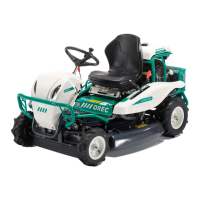
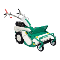
The OREC Grassland Mower Rabbit is designed for mowing grass efficiently and safely. It is a ride-on mower, as depicted in the illustrations, featuring a steering wheel, operator's seat, and various control levers for speed, cutting height, and blade engagement. The machine is not intended for other operations, such as transporting tools or materials, or carrying persons.
Important Technical Specifications
The manual details the specifications for each model: RM882, RM952, and RM982F (4WD).
- Engine:
- RM882: KAWASAKI FS481V (10.8kW) or Briggs & Stratton Vanguard 479cc (11.7kW).
- RM952: KAWASAKI FS541V (11.2kW) or Briggs & Stratton Vanguard 570cc (13.5kW).
- RM982F (4WD): KAWASAKI FS691V (17.2kW) or Briggs & Stratton Vanguard 627cc (17.0kW).
- Transmission: All models feature Hydrostatic transmission.
- Speed:
- Forward Speed: RM882 (0-10 km/h), RM952 (0-12 km/h), RM982F (0-10 km/h).
- Reverse Speed: RM882 (0-7 km/h), RM952 (0-10 km/h), RM982F (0-8 km/h).
- Cutting Width: RM882 (88 cm), RM952 (95 cm), RM982F (97.5 cm).
- Height of Cut: RM882/RM952 (50-110 mm), RM982F (50-120 mm).
- Weight: RM882 (295 kg), RM952 (315 kg), RM982F (355/350 kg).
- Fuel Tank: All models have a 12-liter fuel tank.
- Blade Transmission: Belt-driven for RM882 and RM952, Reduction for RM982F.
- Steering: Rack and pinion for RM882 and RM952, Reduction for RM982F.
- Blade Engagement: Belt tension for all models.
- Blade Speed: RM882/RM952 (1332 tr/rpm), RM982F (1486 tr/rpm).
- Width: RM882 (980 mm), RM952/RM982F (1070 mm).
Usage Features
The mower is designed for user-friendly operation with several controls:
- Speed Control Lever (HST): This lever (1, Fig 5a & 5b) controls forward, reverse, and stop functions. Pushing it forward increases speed, pulling it back decreases speed, and the "N" (Neutral) position stops the machine. Gradual release is advised to prevent sudden stops, except in emergencies.
- Throttle Lever: This lever (2, Fig 5a & 5b) increases engine speed when pushed forward and decreases it when pulled backward. The machine should always be used at full engine speed for mowing.
- Differential Lock Lever: This lever (3, Fig 5a & 5b) engages the rear wheels together in slipping areas. It should be locked only when one wheel is slipping and released once the machine leaves the slipping area. It is crucial not to use the diff lock when turning to avoid transmission damage.
- Sub Change Lever (RM952 only): This lever (4, Fig 5b) controls basic driving speed, offering "Low speed" and "Hi speed" positions. For grass cutting, the "Low speed" position is recommended to reduce machine damage. The "N" (Neutral) position disengages the HST gearbox, allowing the machine to be pushed without engine power.
- Brake (Parking) Pedal: Used for emergency stops or to lock the parking brake (1, Fig 6a & 6b). Pressing the pedal automatically moves the travel speed lever to neutral. To lock the parking brake, press the pedal and turn the locking lever (2) to the right.
- Adjust Handle Tilt and Angle: The handle angle can be adjusted using lever (3, Fig 6a & 6b). It must be securely tightened after adjustment.
- Choke Lever: Used to start a cold engine (4, Fig 6a & 6b) and gradually released as the engine warms up.
- Ignition Key: (5, Fig 6a & 6b) Starts and stops the engine. The key can be removed in the "stop" position.
- Front Pedal (RM982F only): This pedal (6, Fig 6b) controls forward movement, with speed varying by the angle of use.
- Steering Wheel: Changes the machine's direction. Its height can be adjusted by removing a bolt and nut.
- Cutting Height Lever: (1, Fig 7) Adjusts the cutting height. The highest position is for transport. Lowering the lever increases the risk of damage and thrown objects.
- Blade Clutch Lever: (2, Fig 7) Engages the blade when pushed forward and stops it when pulled up. The blade should never be permanently engaged.
- Lateral Guards: Mowing deck side shields should be locked with bolts and nuts during mowing to prevent injury from thrown objects. They can be unlocked for transport.
- Seat: The operator's seat position can be adjusted by pulling up lever (1, Fig 8) and sliding the seat. The suspension strength can also be adjusted based on the user's weight (2, Fig 8).
- Safety Switches: The machine is equipped with safety switches to prevent starting with the blade engaged or brake disengaged, and to cut off the engine if the operator leaves the seat while it's running or if blades are engaged.
- Fuel Cock: (Fig 9) Controls fuel flow. It is open when the lever aligns with the fuel hose and closed when perpendicular.
- Front Light: (Fig 21) Can be switched on from the dashboard.
Maintenance Features
The manual emphasizes regular maintenance for safe and efficient operation.
- General Maintenance:
- Before any maintenance, ensure the cutting blade is disengaged, the engine is stopped, the parking brake is engaged and locked, and the ignition key is removed.
- Daily maintenance is performed by the user.
- First 20 hours, 100 hours, and 300 hours maintenance should be inspected by a dealer.
- Keep the machine clean and free from debris.
- Check all shields, grids, and safety guards are in place and in good condition.
- Check for oil leaks and hydraulic hose condition.
- Ensure safety instruction stickers are in place and legible.
- Tighten all bolts and screws to the specified torque.
- Lubricate grease nipples.
- Store the machine in a dry and protected area with the ignition key removed.
- Transmission (Gear) Oil Level: (Fig 12)
- Check on a flat surface. Oil level should be at the lowest point of window (C).
- Add SAE 90 or API GL-5 oil if needed.
- Drain oil from plug (A).
- Capacity: 1.00L.
- Replacement frequency: First replacement after 20 hours, then every 100 hours or yearly.
- HST Oil Level: (Fig 14)
- Check regularly on a flat surface. Oil level should reach "FULL".
- Add "VG46" or "SAE 10W30" oil of the same type. Do not mix different types.
- Capacity: 0.50L (RM882/RM952), 5.0L (RM982F).
- Check for oil leaks.
- Rear HST Oil Replacement: (Fig 13, Fig 14)
- Replace HST oil and filter frequently to ensure smooth working.
- Drain used oil by removing the oil drain plug (1, Fig 13).
- Refill with recommended oil, ensuring no dust mixes with it.
- Front HST Oil Drain (RM982F): (Fig 16)
- Drain oil from the drain bolt on each side of the wheel. If oil doesn't drain well, remove the Air release plug and Oil cap.
- Torque for drain bolt: 15N·m±10%.
- Replacement frequency: First replacement after 20 hours, then every 200 hours or yearly.
- Refer to the color and smell of HST oil to determine its status (clean, black, milky white) and necessary action (use as usual, filter, or change).
- Bleeding Hydrostatic Transmission System:
- After HST oil replacement, air may enter the system.
- Tilt the change lever halfway to FORWARD and BACKWARD for 10 seconds, then return to neutral. Repeat 5 times at idling throttle.
- Check for bubbles in the HST oil tank and add oil if needed to the "High level position".
- Fuel:
- Check fuel tank level (1, Fig 17). Refuel when the needle indicates "E".
- Ensure the tank cap (2, Fig 17) is fully closed and check for leaks.
- Use only good quality gasoline.
- When working on slopes, keep the fuel tank half full to avoid leaks.
- Flammable Materials: Remove flammable materials, especially near hot parts like the muffler or engine, to prevent fire.
- Steering: (Fig 18)
- Check vertical gap (max 1mm) and lateral gap (max 40mm).
- Tires: (Fig 19)
- Check for cuts, cracks, or wear.
- Check tire pressure: 1.2 bar front, 1.4 bar rear.
- Safety Stickers: Ensure they are correctly placed and in good condition. Replace if worn or damaged.
- Lateral Guards and Shields: Check that they are fixed.
- Electrolyte Battery Level: (Fig 20)
- Check that the level is between upper and lower marks. Add distilled water if necessary.
- Exercise caution when maintaining the battery; avoid flames and sparks, wear gloves and glasses, and wash with water if electrolyte touches skin.
- Engine: Refer to the engine owner's manual for specific maintenance.
- Kawasaki: Check oil level (1, Fig 31) when the engine is not hot. Oil should be between the two marks. Drain oil after the first 8 hours, then every 100 hours or yearly. Use SAE 10W30 or APL SL class oil. Capacity: 1.7L (RM882/RM952), 2.1L (RM982F).
- Briggs & Stratton: Check oil level by gauge "A" (Fig 32) after 5 minutes of engine stop on a flat surface. Add engine oil if necessary. Drain oil by plug C.
- Air Filter:
- Kawasaki: (Fig 25, Fig 26, Fig 27, Fig 28) Remove cover, unscrew screws (A) and collar (B). Blow cartridge with low air pressure from inside to outside. Clean foam with water and soap, dry and oil with engine oil. Replace cartridge if too dusty. Do not blow at high pressure.
- Briggs & Stratton: (Fig 29, Fig 30) Remove filter by clips "A", unscrew wing nut (1). Clean foam with water and soap, dry and oil with motor oil. Blow cartridge with low air pressure from inside to outside. Replace cartridge if too dusty. Do not blow at high pressure.
- Fuel Filter:
- Kawasaki: (2, Fig 31) Check for dirt or water. Clean or change if necessary.
- Briggs & Stratton: (Fig 9, Fig 32) Check for water and dust in the fuel cartridge filter cock and filter. Clean or replace if dirty.
- Belt Tension: (Fig 33)
- Check belt condition and replace if worn or damaged.
- If the belt is slipping, tighten the wire with adjusting nut (B).
- If the brake belt doesn't stop the blade in 5 seconds, tighten the wire with adjusting nut (A).
- Improper belt tension can cause slipping, wear, and damage to bearings.
- Brake: (Fig 34) If the brake is not working efficiently, tighten it with the nut.
- Tightening of Bolts: Regularly check that all bolts and nuts are properly tightened, as vibrations can loosen them.
- Adjust Safety Switches: Adjust screws to push safety switches 3 to 5 mm.
- Travel Lever Adjustment: (A, Fig 35) Adjust the control link so the machine is motionless when the speed control lever is in neutral.
- Diff Lock Lever Adjustment: (B, Fig 35) Adjust the control rod to have a free play of 1 to 3 mm before activating the diff lock.
The manual also includes a detailed maintenance chart outlining inspection points and frequencies for various components. It provides a troubleshooting guide for common breakdowns and their solutions, as well as a table of tightening torques for screws of different diameters. EC Conformity Declarations for each model, including measured vibration levels, are also provided, along with a limited warranty statement.