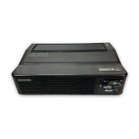
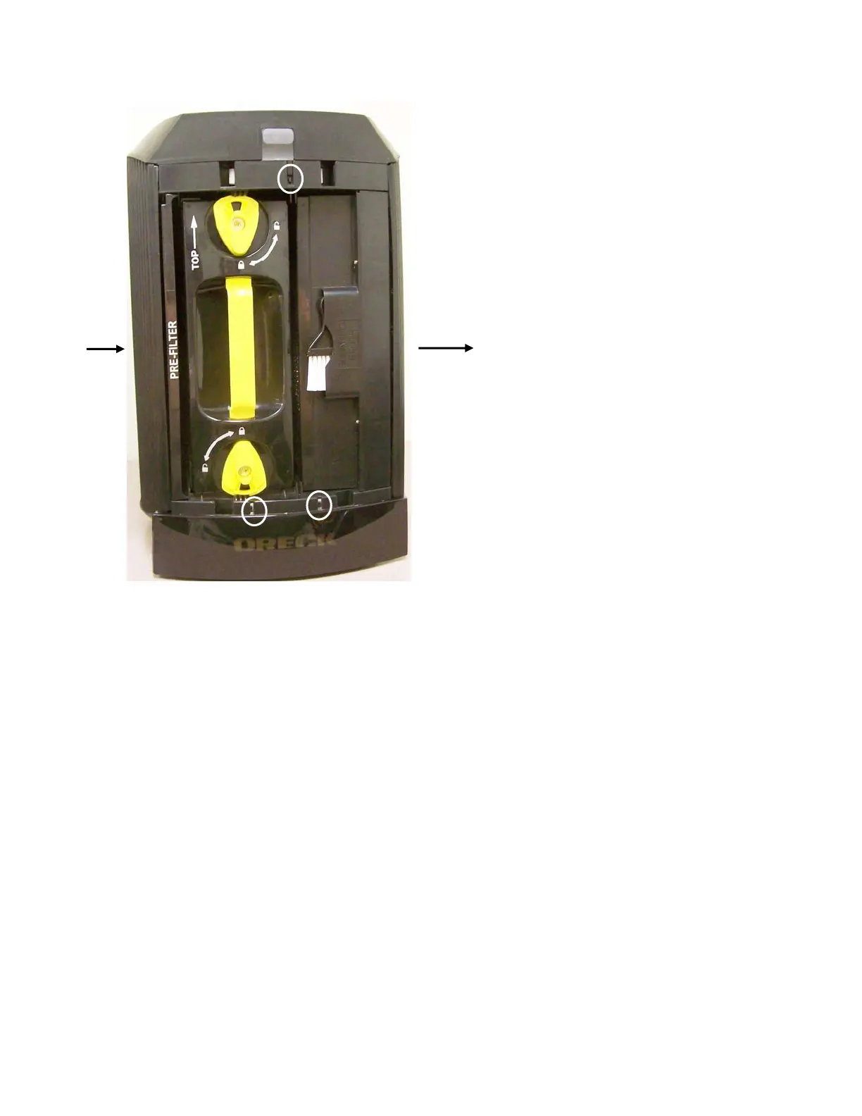
Control Section Inside Top
Remote Control Sensor Window
PCO
Module
All Safety Interlock Switches are circled except
the PCO Module Sense Switch.
The Cell Sense Switch is not a safety switch.
Exhaust
Intake
Cell
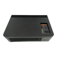
Power Section Inside Base
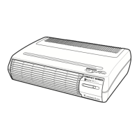
Disassembly
Remember to start with a clean bench and a tray to put the screws in.
Be sure the unit is NOT plugged in while servicing except to test functions.
The unit is constructed so that once the front cover, prefilter, cell and PCO module are
removed (you’ve already done this one during the Tune-up), the back, control section
and power section can be worked on individually.
To remove either Intake or Exhaust Grills, the Control Section and Power Section must
be removed to access the grill screws.
If you remove either grill keep in mind that when reinstalling, the end with the deep ribs
is down and the end with the shallow ribs is up.
If you remove either the Top or Base make sure the wires are not laying across a screw
boss when reassembling.
8
 Loading...