13
- insert the screw into the slot (photo 3).
- position the rear protection (photo 4A).
- secure the handle on the screw (photo 4B).
- position the wheel guard properly (foto 6A - 6B), by rotating it till the notch hits the arm (foto 6C) and secure it with the position lock
screw (foto 6D).
using exclusively OEM spare parts, otherwise whoever uses the
machine could be in serious danger.
- Use a proper electric tool.
- Do not use low effective tools for heavy duty applications.
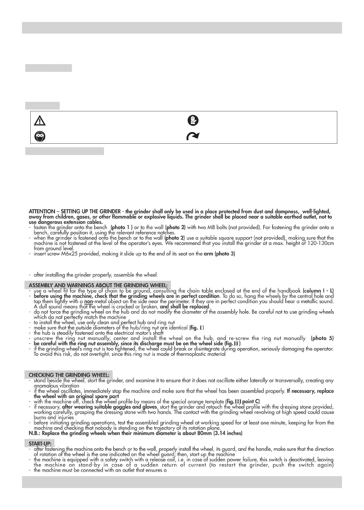
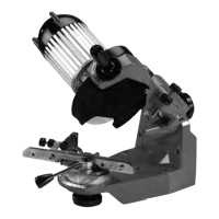
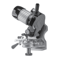
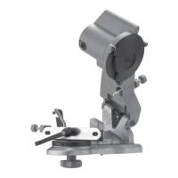
This machine is an electrical grinder for chains used in chain saws.
- Use the machine exclusively for the types of chains stated in the
technical data chart.
- Do not use the machine to cut or grind anything other than the
chains envisaged.
- The machine must not be used in corrosive or explosive
environments.
- Any other use is to be considered improper.
The manufacturer is not liable for damages following improper or
incorrect use of the machine.
SYMBOLS
This symbol points out the possibility of serious personal
injuries if the provisions and instructions are not complied
with.
This symbol points out that the user must wear protective
gloves when he uses the machine.
This symbol points out that the user must wear protection
goggles when he uses the machine.
This symbol points out the correct running direction of the
machine (grinding wheel)
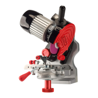
PART DESCRIPTION (FIG. iv)
1. Depth adjustment knob
2. Grinding wheel, 3/16”
3. Front protection
4. Large washer
5. Flange nut
6. Shield guard screw
7. Knob
8. Vise assembly
9. Dressing brick
10. Template
11. Handle bolt
12. Operating handle
13. Rear protection
Note: for spare sarts, see vi.
INTENDED USE
230 Volt